| Image |
Instructions |
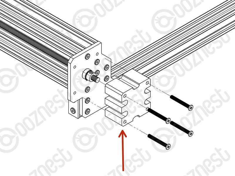 |
- Remove all Lead-Screw-Caps from the X, Y-Left & Y-Right Axis.
|
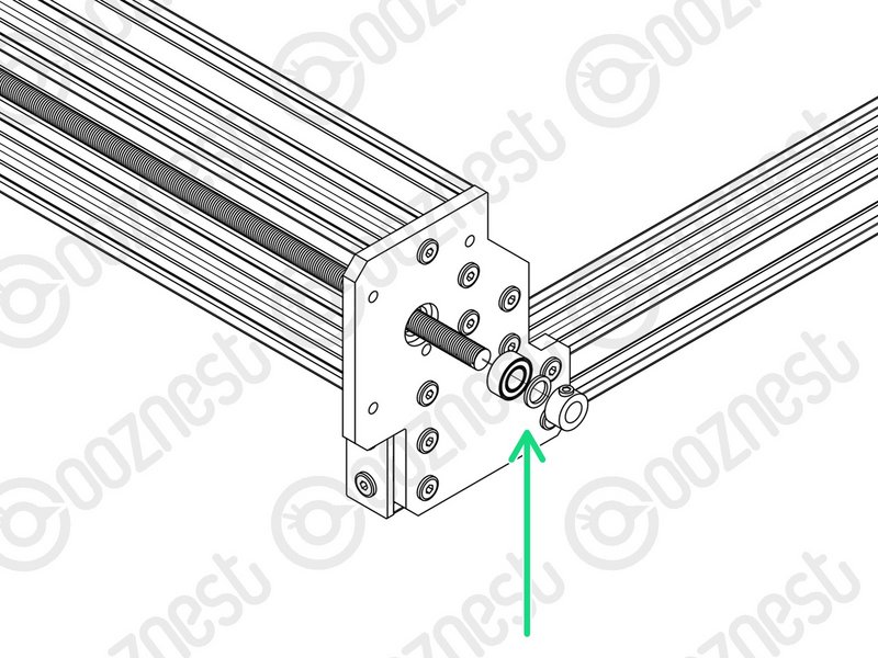 |
- You will need to put these back later. So put them in a safe place.
- From underneath the Lead-Screw-Caps, remove the Clamping-Collars, Bearing-Shims & Flanged-Radial-Bearings.
- We supply new parts to replace these. So they can be discarded, or kept for spares.
|
| Image |
Instructions |
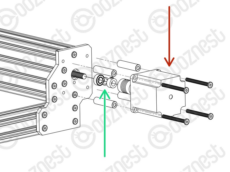 |
- Loosen the Flexible-Coupler from the Stepper-Motor and Lead-Screw on the X, Y-Left & Y-Right Axis.
- Disconnect and remove the Stepper-Motors, M5-Low-Profile-50mms and 4 x Aluminium-Spacer-40mms.
- You will need to put these back later. So put them in a safe place.
- Remove the Clamping-Collars, Bearing-Shim & Flanged-Radial-Bearings.
- We supply new parts to replace these. So they can be discarded, or kept for spares.
|
| Image |
Instructions |
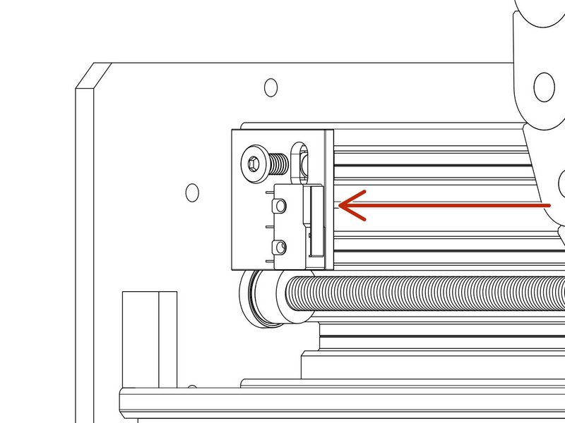 |
- The X-Limit-Switch-Mount is going to be replaced later in the guides.
- Take the X-Limit-Switch-Mount off the machine.
- Remove the Limit-Switch from X-Limit-Switch-Mount. Leave the Limit-Switch hanging from the X-Gantry.
- Put the 2 x M3-Plastite-Screw-8mm, M5-Low-Profile-8mm and M5-Drop-In-Tee-Nut in a safe place.
|
Repeat the below X-Axis, Y-Left & Y-Right Axis.
| Image |
Instructions |
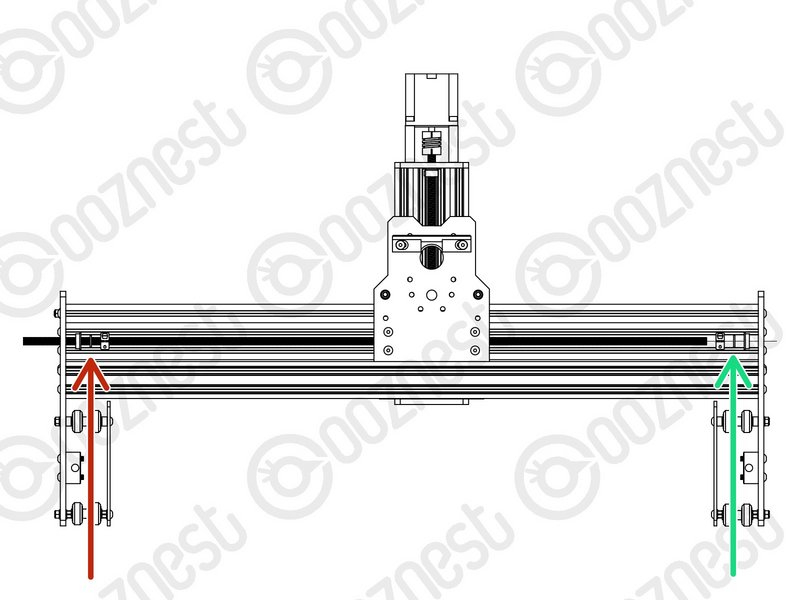 |
- Thread back the Lead-Screw so the end of it is on the inside of the extrusion channel.
- Then slide onto the Lead-Screw a Clamping-Collar -> Rubber-Bushing -> Flanged-Radial-Bearing.
- Repeat for the opposite end of the Lead-Screw.
|
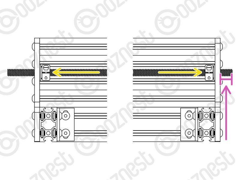 |
- Adjust the Lead-Screw so there is 14mm protruding from the Stepper-Motor side of the X-Axis.
- Seat the Flanged-Radial-Bearings into the Y-Carriages, slide the Rubber-Bushing against the Flanged-Radial-Bearings and finally slide the Clamping-Collars so they are against against the Rubber-Bushings.
- Slightly tighten the Clamping-Collars.
|
Thrust-Bearings come in 3 parts. Thrust-Bearing-Housing-Washer, Thrust-Bearing-Caged-Roller and Thrust-Bearing-Shaft-Washer
The Thrust-Bearing-Housing-Washer and Thrust-Bearing-Shaft-Washer look exactly the same. They are not.
The Thrust-Bearing-Shaft-Washer has a smaller internal diameter thus it will be tighter on the Lead-Screw.
We recommend adding a generous amount of bearing Lubricant to the grooved face of both washers.
Repeat the below X-Axis, Y-Left & Y-Right Axis.
| Image |
Instructions |
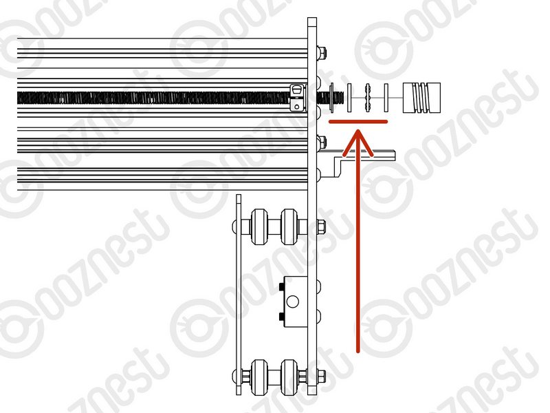 |
- On the Stepper-Motor side slide on a Nylon-Shoulder-Washer -> Thrust-Bearing-Housing-Washer -> Thrust-Bearing-Caged-Roller -> Thrust-Bearing-Shaft-Washer
- The Nylon-Shoulder-Washer seats in the 16mm hole on the Y-Carriage.
|
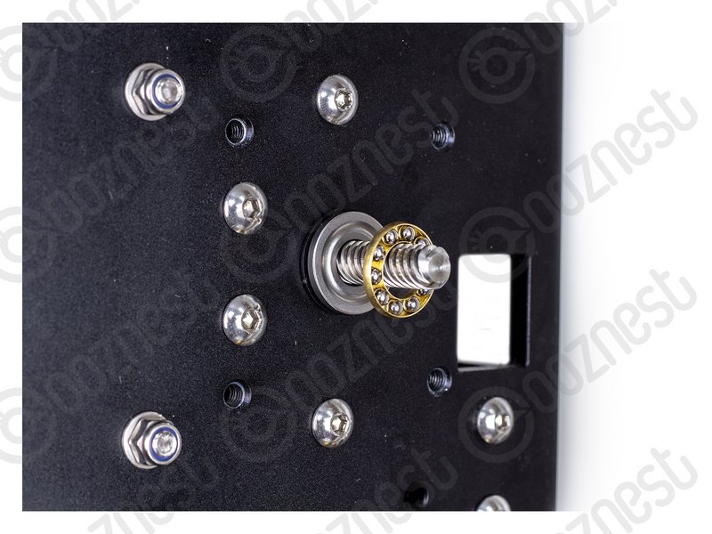 |
- The Thrust-Bearing-Caged-Roller seats in the grooves on the Thrust-Bearing washers. Look at Image 3 for the correction orientation of the Thrust-Bearing-Caged-Roller.
|
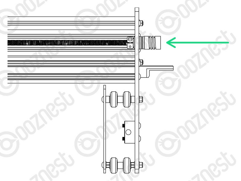 |
- Finally slide on a Flexible-Coupler. While pushing the Flexible-Coupler against the Thrust-Bearing assembly, tighten Flexible-Coupler.
- On the Flexible-Coupler tighten the clamping bolt first and then the grub screw.
|
Thrust-Bearings come in 3 parts. Thrust-Bearing-Housing-Washer, Thrust-Bearing-Caged-Roller and Thrust-Bearing-Shaft-Washer
The Thrust-Bearing-Housing-Washer and Thrust-Bearing-Shaft-Washer look exactly the same. They are not.
The Thrust-Bearing-Shaft-Washer has a smaller internal diameter thus it will be tighter on the Lead-Screw.
We recommend adding a generous amount of bearing Lubricant to the grooved face of both washers.
Repeat the below X-Axis, Y-Left & Y-Right Axis.
| Image |
Instructions |
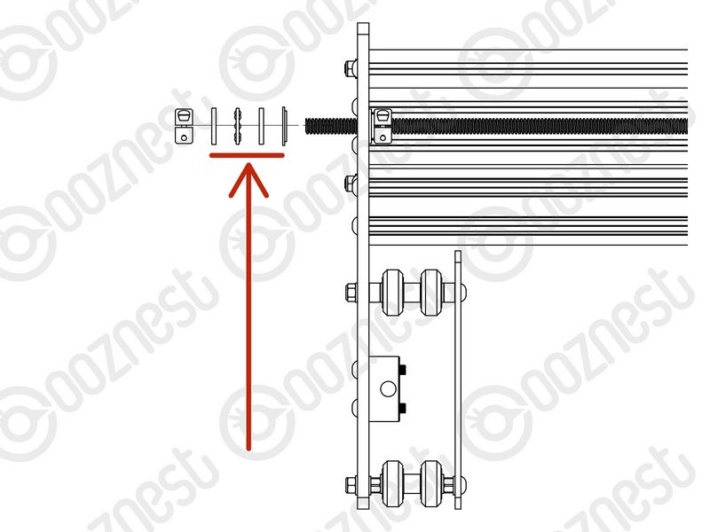 |
- On the opposite side to the Stepper-Motor slide on to the Lead-Screw a Nylon-Shoulder-Washer -> Thrust-Bearing-Housing-Washer -> Thrust-Bearing-Caged-Roller -> Thrust-Bearing-Shaft-Washer
- The Nylon-Shoulder-Washer seats in the 16mm hole on the Y-Carriage.
|
 |
- The Thrust-Bearing-Caged-Roller seats in the grooves on the Thrust-Bearing washers. Look at Image 3 for the correction orientation of the Thrust-Bearing-Caged-Roller.
|
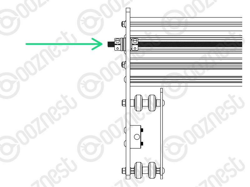 |
- Finally slide on a Clamping Collar. While pushing the Clamping-Collar against the Thrust-Bearing assembly, tighten the Clamping-Collar.
|
| Image |
Instructions |
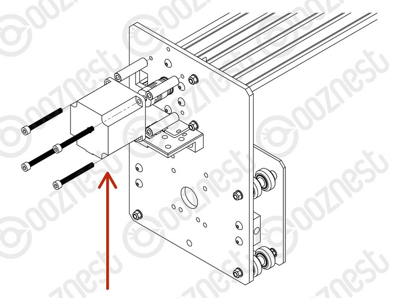 |
- Reattach and reconnect all Stepper-Motors using the previously removed M5-Low-Profile-50mms and 4 x Aluminium-Spacer-40mms
- On the Stepper-Motor side make sure the Flexible-Coupler grub screw is on the flat portion of the Stepper-Motor shaft.
- Once in position, tighten the clamping bolt first, then the grub screw.
- The Lead-Screw side was tightened earlier in this guide.
|
For the below A Pozi #1 Screwdriver should be used. The best technique is to thread into the Limit-Switch a small amount, then back out. Then back in further, back out, so on so fourth until the Limit-Switch is secure.
Do not over tighten as you can shatter the switch. Make sure the Limit-Switch is orientated correctly.
| Image |
Instructions |
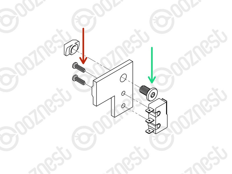 |
- Attach the X-Axis Limit-Switch to the X-Limit-Switch-Mount using the previously removed 2 x M3-Plastite-Screw-8mm.
- The M3-Plastite-Screw-8mm's go through the X-Limit-Switch-Mount first, then self thread into the Limit-Switch.
- Insert the previously removed M5-Low-Profile-8mm through the hole on the X-Limit-Switch-Mount and slightly thread on the M5-Drop-In-Tee-Nut.
|
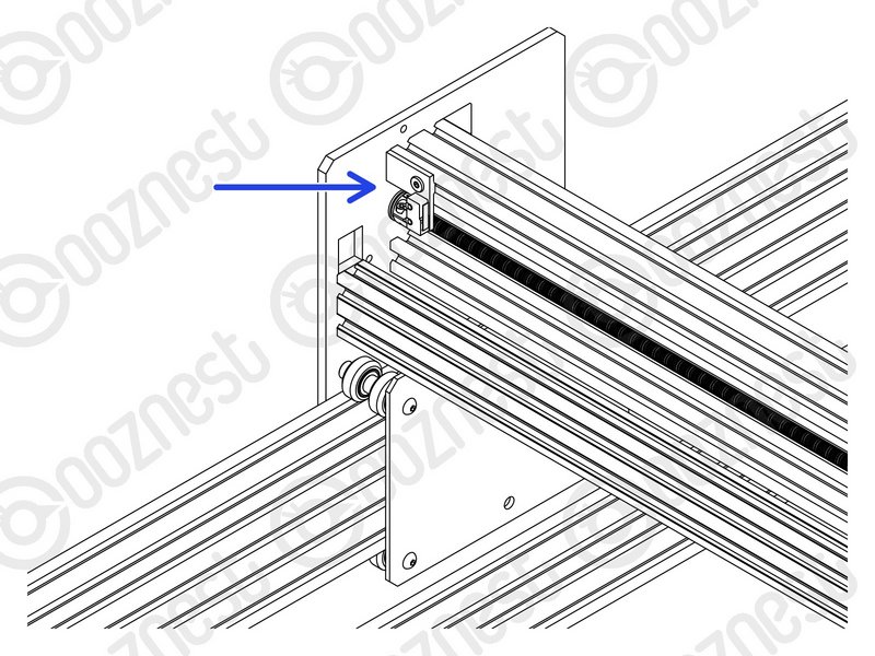 |
- Attach the X-Limit-Switch-Mount to the back of the X-Gantry C-Beam. It should be at the left side if looking from the back. The X-Limit Switch-Mount should be up against the Y-Carriage.
|
| Image |
Instructions |
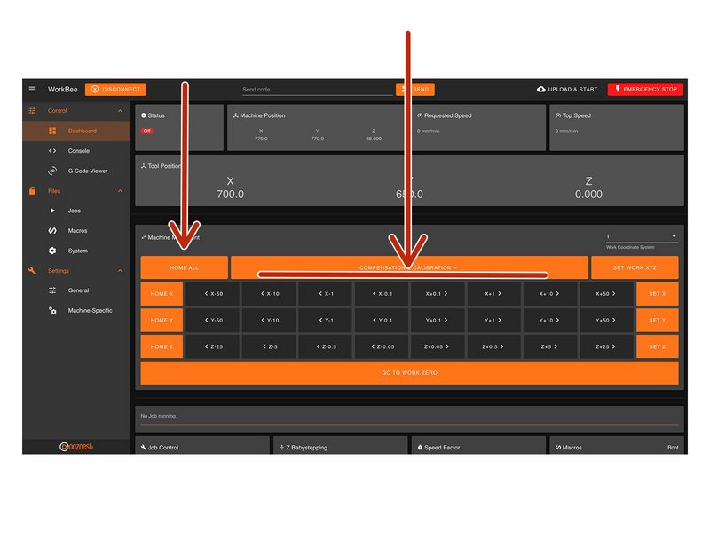 |
- Home the machine and use the jog buttons to move the machine roughly into the middle of the working area.
- Loosen all the Nut-Blocks on the X & Y-Carriages.
|
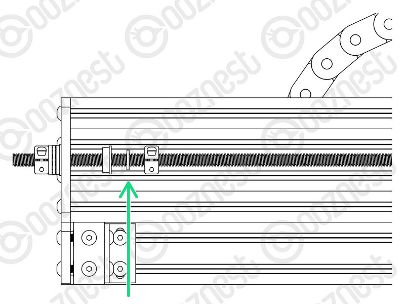 |
- Loosen the Clamping-Collars that are on the inside of the extrusion channel on the X & Y Axes.
- Move all Flanged-Radial-Bearings, Rubber-Bushings & Clamping-Collars away from the plates.
|
Repeat the below X-Axis, Y-Left & Y-Right Axis.
| Image |
Instructions |
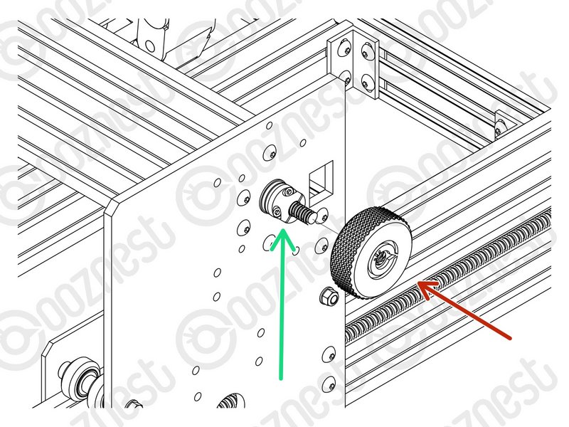 |
- Thread on the Tensioning-Knob until it is up against the Clamping-Collar.
- Then loosen the same Clamping-Collar.
- Turn the Tensioning-Knob clockwise, you will feel the Lead-Screw tension build.
- Keep turning until the Stepper-Motor clicks over.
- Keep turning, just before the point that the Stepper-Motor clicks over is the correct amount of tension for the Lead-Screw.
- While at this point of tension, tighten the Clamping-Collar that is next to the Tensioning-Knob.
|
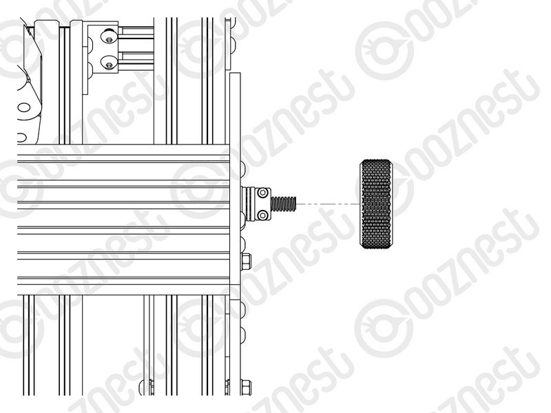 |
- Remove the Tensioning-Knob.
|
Repeat the below X-Axis, Y-Left & Y-Right Axis.
| Image |
Instructions |
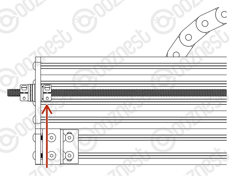 |
- Put back the Flanged-Radial-Bearings, Rubber-Bushings, and Clamping-Collars that are on the inside of the extrusion channel on the X & Y Axes.
- The Clamping-Collars only need to be pushed lightly up against the Rubber-Bushings & Flanged-Radial-Bearings.
|
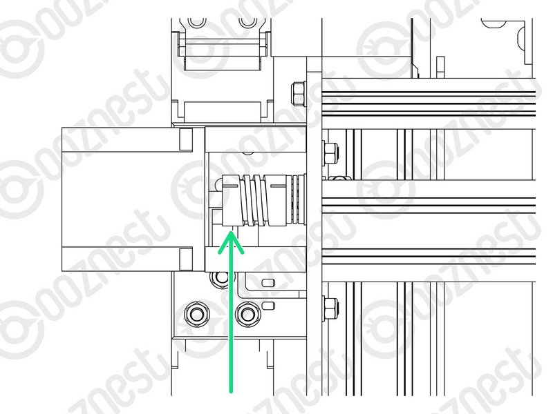 |
- We need to release any tension inside the Flexible-Couplers.
- On the Stepper-Motor side of the X & Y-Axis Flexible-Couplers completely loosen the grub screws and clamping bolts.
- Then completely tighten the same grub screws and clamping bolts.
- Make sure you do this to the Stepper-Motor side of the Flexible-Coupler. If you loosen the Lead-Screw side you will loose all tension in the Lead-Screws and you will need to redo it.
- Tighten all the Nut-Blocks on the X & Y-Carriages. While doing so, squeeze the Nut-Blocks together to remove any backlash.
|
| Image |
Instructions |
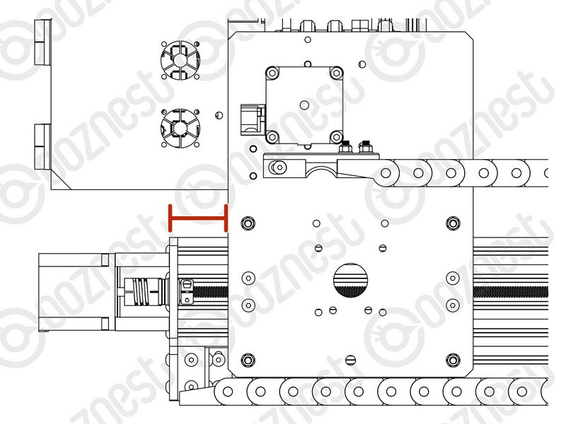 |
- Home the machine.
- Then turn the machine off.
- On the left Y-Axis (The side with the Limit-Switch) measure the distance between the back of the Y-Carriage and Y-End-Plate.
|
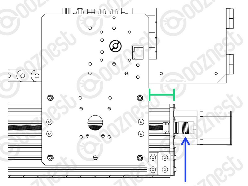 |
- On right Y-Axis measure the same distance.
- Rotate the Flexible-Coupler by hand until it matches the left Y-Axis.
|
| Image |
Instructions |
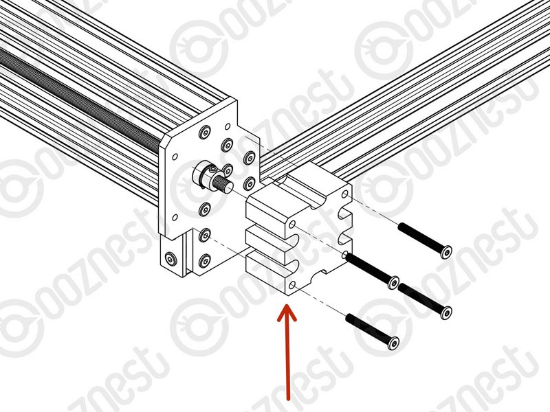 |
- Put back the Lead-Screw-Caps removed in Step 1.
|