| Image |
Instructions |
 |
- Disconnect all wires to the Controller.
- Remove the old mount and all hardware.
|
To assemble the new Controller Case, only the Controller and Wires are needed.
All other parts removed can be discarded.
| Image |
Instructions |
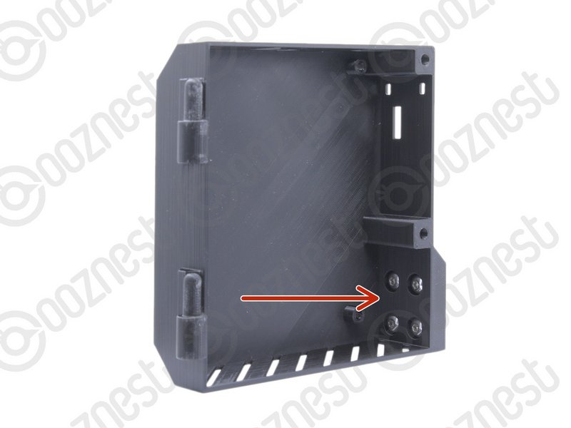 |
- Insert 4 x M5-Button-Head-Bolt-12mm through the holes on the Controller-Case-Body
|
 |
- Slightly thread a M5-Drop-In-Tee-Nut onto each bolt.
|
| Image |
Instructions |
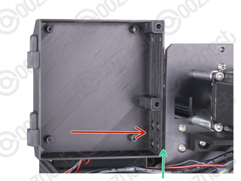 |
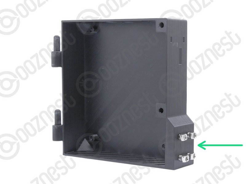
- Join the Controller-Case-Body to both slots on the back of X-Gantry 20x40 Extrusion. Using the previously inserted M5-Button-Head-Bolt-12mm.
|
 |
- It should be pushed up against the Y-Carriage.
- Using a 3mm Hex Key Ball driver would be easiest.
- Make sure the M5-Drop-In-Tee-Nuts are engaged with the slots on the Extrusion.
|
If you have the Wifi Controller with the External Antenna, the External-Antenna is made up of 5 pieces: Antenna-Arm, Antenna-Wire, Spring-Washer, Star-Washer and Hex-Nut.
| Image |
Instructions |
 |
- For the Wifi version with the External Antenna, before putting the Controller inside the Controller-Case plug the Antenna-Wire into the Wifi module until it clicks.
- Mount the Controller to the Controller-Case-Body using 4 x M4-Cap-Head-Bolt-16mm and 4 x M4-Nyloc-Nut.
- The 4 x M4-Nyloc-Nuts go on the back of the Controller-Case-Body.
- Make sure the Controller is orientated correctly with the two large green terminals at the bottom.
|
| Image |
Instructions |
 |
|
| Image |
Instructions |
 |
- Gather all the wires coming of Drag-Chain-Y.
- Neatly twist the wires together to form a consistent cylinder of wires. It should look like Image 1.
- Include the Ethernet-Cable in this bundle.
|
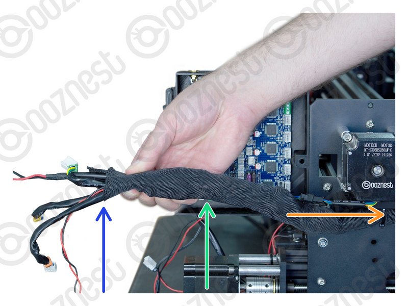 |
- Wrap the provided Cable-Sleeve around all the wires.
- The Cable-Sleeve should not go right to the end.
- Excess Cable-Sleeve can go inside Drag-Chain-Y.
|
| Image |
Instructions |
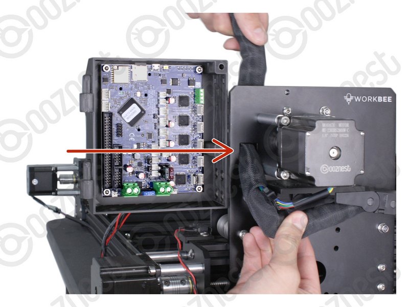 |
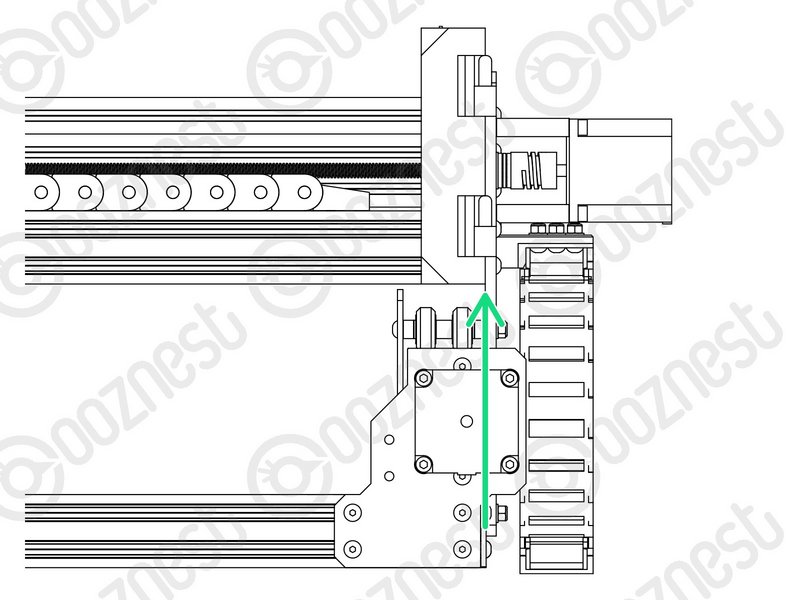
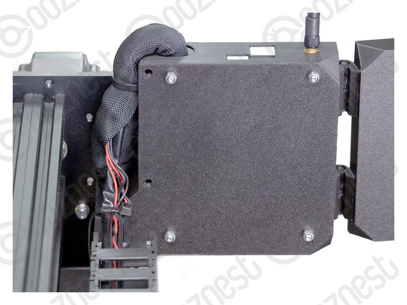
- Feed the twisted bundle of wires through the square hole on the Y-Carriage.
|
 |
- Then run it up the side of the Controller-Case-Body and into the large hole on the top.
- Do not put the Ethernet Cable through this hole. Slip it out of the Cable-Sleeve.
- Roughly 50mm of Cable-Sleeve should be protruding into the Controller-Case-Body.
- Take your time to tidy up the Cable-Sleeve, and feed any back into the Drag-Chain-Y.
|
| Image |
Instructions |
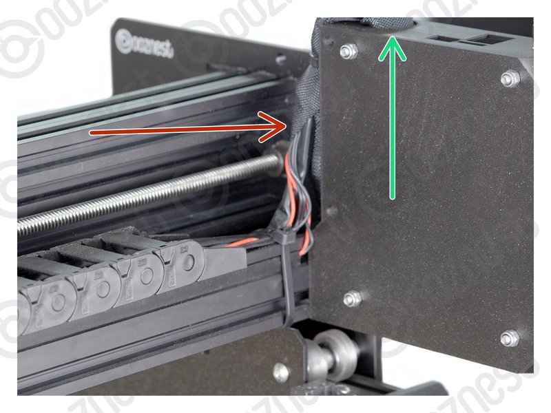 |
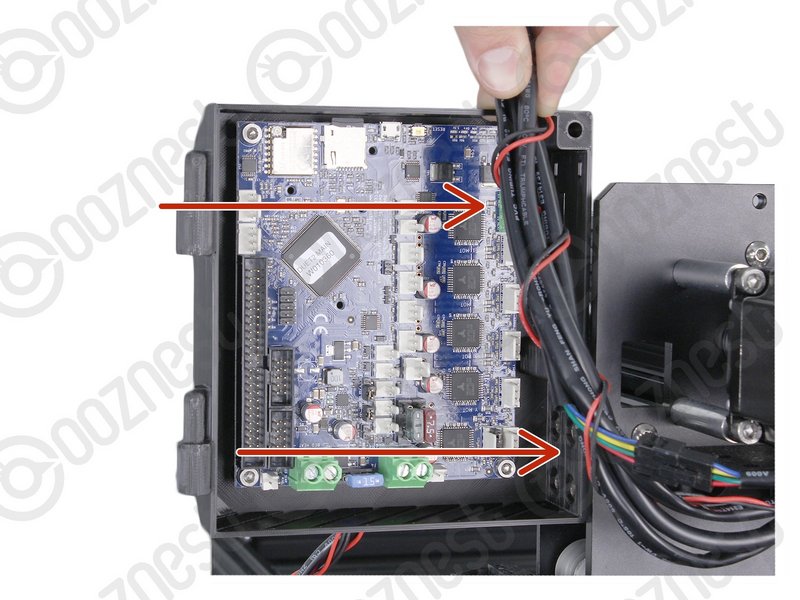
- Bring the wires from Drag-Chain-X & Limit-Switch-0, up into the side of the Cable-Sleeve.
- Feed them through the same hole in the top of the Controller-Case-Body
|
Make sure your Power Supply is not plugged in.
| Image |
Instructions |
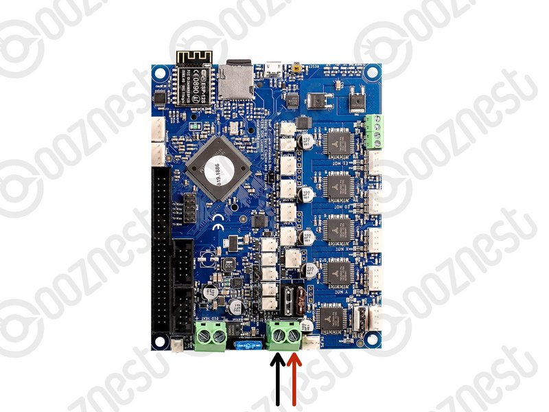 |
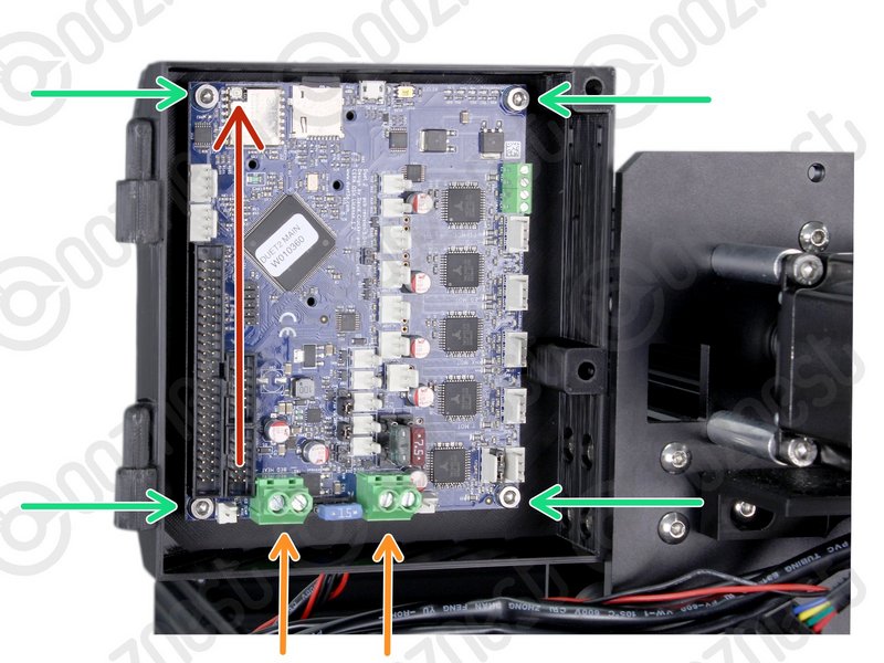
- Connect the output wire of the Power Supply into the input screw terminal on the Controller.
- Use an Insulated Flathead Screwdriver.
|
| Image |
Instructions |
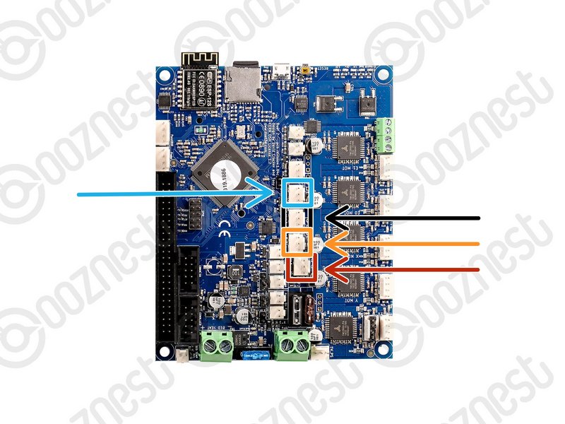 |
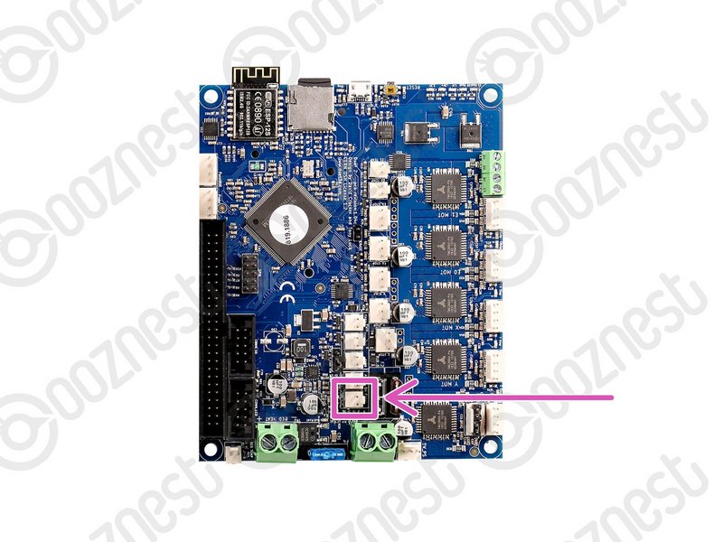
- The connectors on the wires are keyed, so there is only one way which they can plug in.
- Plug in the limit switch wires following Image 1.
- Limit-Switch-0 (X-Axis)
- Limit-Switch-1 (Y-Axis)
- Limit-Switch-2 (Z-Axis)
- The Touch Probe wire can also be plugged in.
|
| Image |
Instructions |
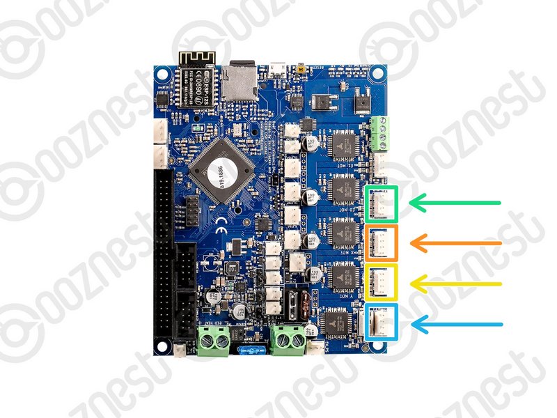 |
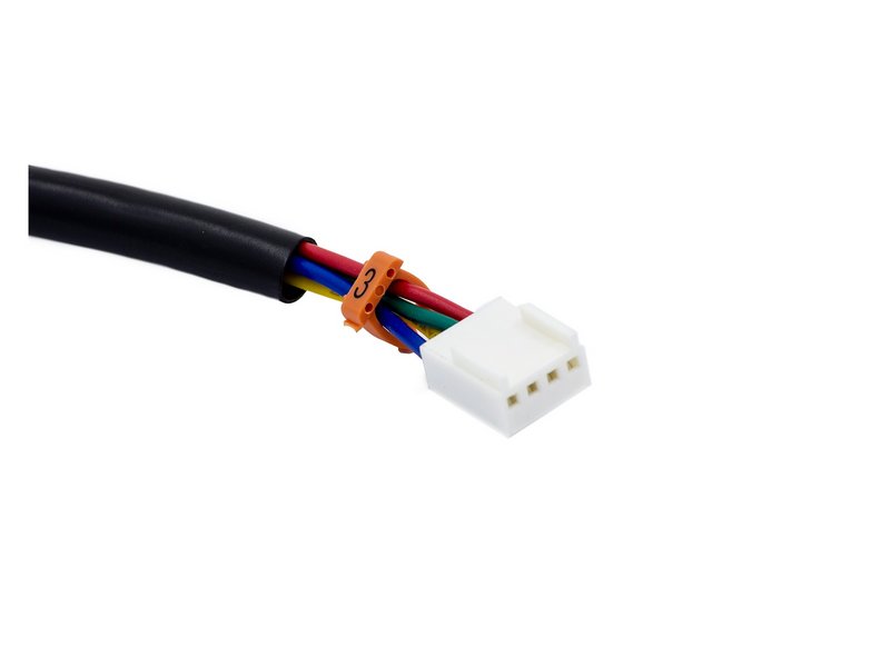
- Plug in the motor wires following Image 1.
- Motor-Wire-5 (Y-Axis-Right)
- Motor-Wire-3 (X-Axis)
- Motor-Wire-4 (Y-Axis-Left)
- Motor-Wire-6 (Z-Axis)
|
If you have the Wifi Controller with the External Antenna please complete this Step. Otherwise, skip to the next Step.
The External-Antenna is made up of 5 pieces: Antenna-Arm, Antenna-Wire, Spring-Washer, Star-Washer and Hex-Nut.
| Image |
Instructions |
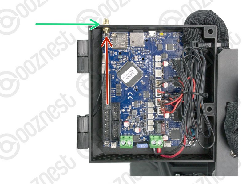 |
- Insert the threaded portion of the Antenna-Wire up into the hole of the Controller-Case-Body.
- The Spring-Washer should be in between the shoulder of Antenna-Wire and Controller-Case-Body.
|
 |
- On the outside of the Controller-Case-Body add the Star-Washer, and then thread on the Hex-Nut.
- Tighten this assembly.
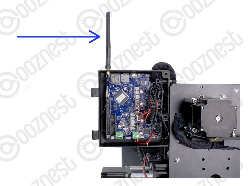
- Screw on the Antenna-Arm.
|
| Image |
Instructions |
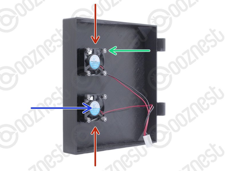 |
- Mount the Controller-Fans to the Controller-Case-Cover using 8 x M3-Button-Head-Bolt-16mm & 8 x M3-Nyloc-Nut.
- The Controller-Fans go on the inside of the Controller-Case-Cover.
- The M3-Nyloc-Nuts should be on the inside of the Controller-Case-Cover.
- The stickers on the Controller-Fans should be visible.
|
 |
- Hook the Controller-Case-Cover onto the hinges on the Controller-Case-Body.
|
| Image |
Instructions |
 |
- Bundle the excess cable inside the Controller-Case and add a small cable tie around the bundle.
|
 |
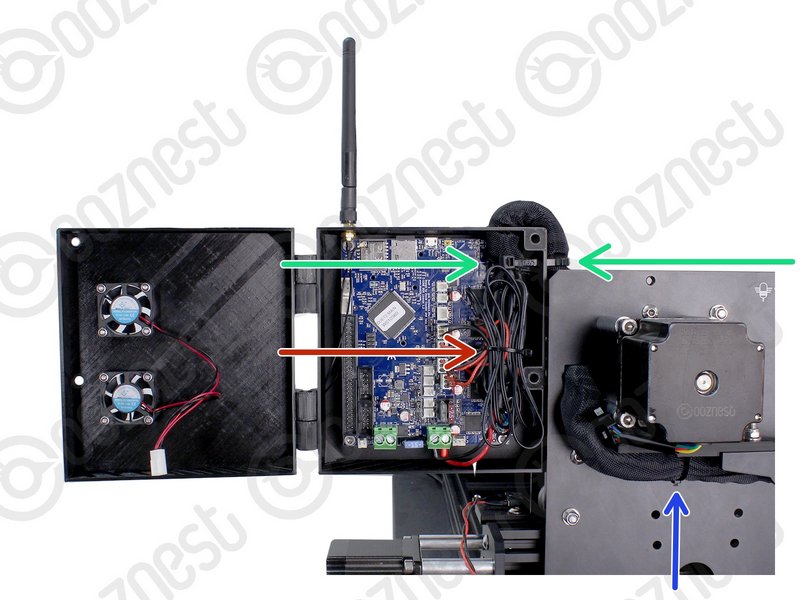
- On the side of the Controller-Case use a large cable tie to secure the bundle of wires inside of the Cable-Sleeve to the Controller-Case.
- The large cable tie should go around the Cable-Sleeve bundle inside and outside the Controller-Case to sandwich it all together.
|
 |
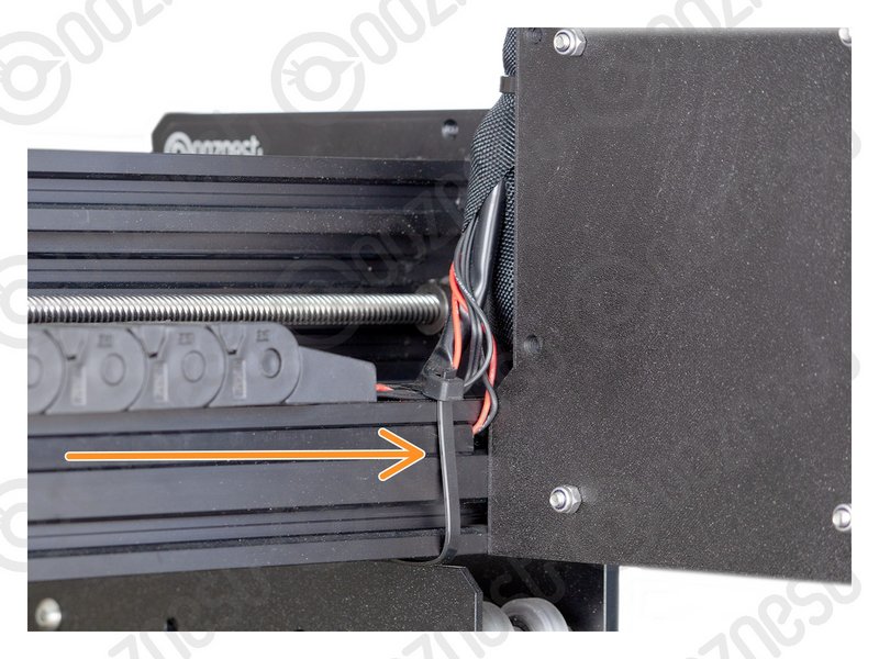
- Tidy up the Cable-Sleeve on the outside controller and feed any excess back into Drag-Chain-Y.
- Use a large cable tie to secure the bundle to the Drag-Chain-Mount.
- Use a large cable tie to secure the wires from Drag-Chain-X & Limit-Switch-0 to Extrusion-B
- Make sure your wires look nice and neat.
|
| Image |
Instructions |
 |
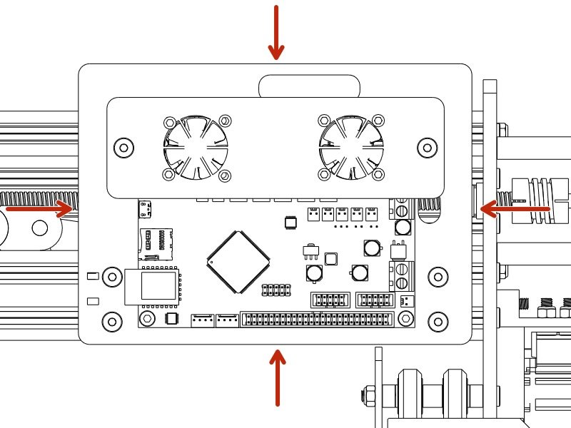
- Plug the Controller-Fans into the Controller.
|
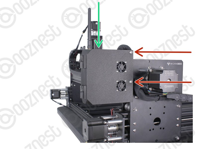 |
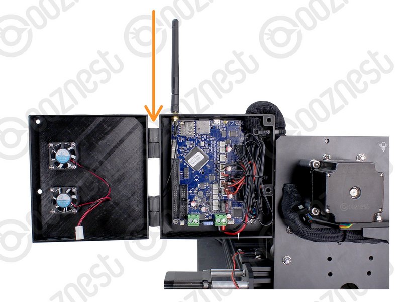
- Close the Controller-Case-Cover to the Controller-Case-Body.
- Secure it using 2 x M5-Button-Head-Bolt-60mm and 2 x M5-Nyloc-Nut.
- The 2 x M5-Nyloc-Nuts go on the back of the Controller-Case-Body.
- If you have the Ethernet version of the controller, you can now plug the Ethernet-Cable into the top of the Controller.
|
| Image |
Instructions |
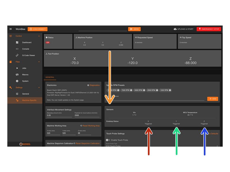 |
- On the same page, under the Panel called 'Sensors' we can test the Limit Switches.
- Activate the X-Axis limit switch with your finger and hold.
- The Endstop Status should change to 'Triggered'
- It is normal for there to be a delay between pressing the limit switch and the status being updated. Please do not be concerned, the board will stop the motor instantaneously.
- Repeat this procedure for the Y-Axis Limit Switch.
- Repeat this procedure for the Z-Axis Limit Switch.
|