| Image |
Instructions |
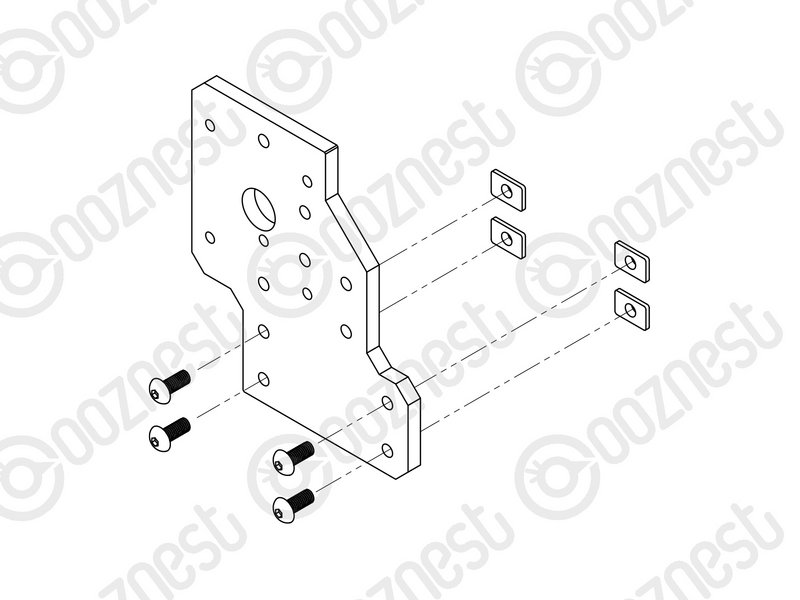 |
- Prepare 2 x Y-End-Plate in the orientation shown in the image, with a M5-Button-Head-Bolt-12mm through each of the 4 bottom holes and a M5-Tee-Nut slightly threaded onto each one.
- The flat side of the M5-Tee-Nut should be facing the Y-End-Plate.
|
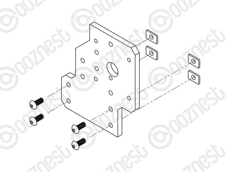 |
- Repeat the above 2 points, but for 2 x Y-End-Plate in the orientation shown Image 2.
|
| Image |
Instructions |
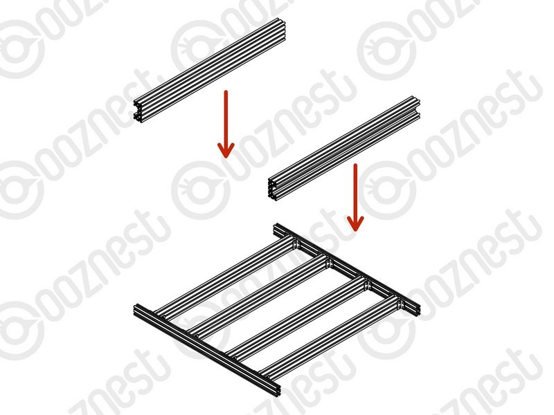 |
- Position the two Extrusion-F's on top of the Base-Assembly.
|
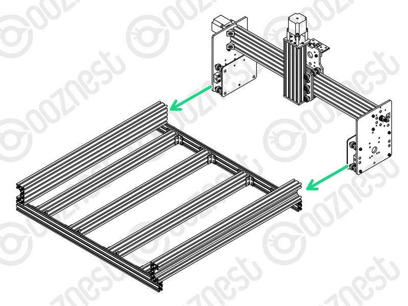 |
- Carefully slide the Y-Carriages on the X-Gantry through the Extrusion-F's
|
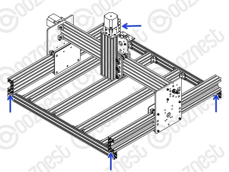 |
- Adjust the position of each Extrusion-F so the ends are flush with the corners of the Base-Assembly.
|
| Image |
Instructions |
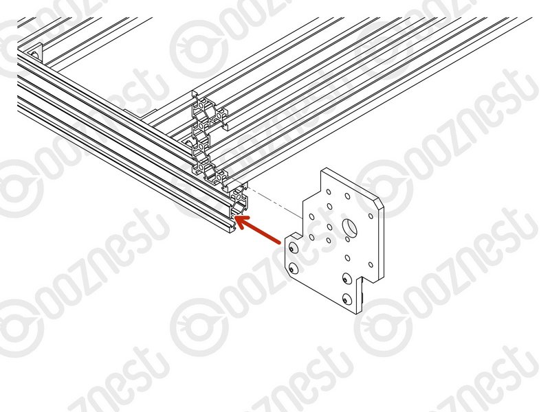 |
- At the front right corner of the machine, slide a Y-End-Plate into the two front-facing slots of Extrusion-A.
|
 |
- Attach the Y-End-Plate to Extrusion-F using 4 x M5-Button-Head-Bolt-16mm through the non-threaded holes on the Y-End-Plate and into the threaded holes on Extrusion-F.
- Make sure the side of the Y-End-Plate is flush with the end of Extrusion-A.
- Then tighten all the M5-Button-Head-Bolt-12mm on the Y-End-Plate.
|
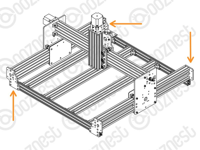 |
- Repeat for the other 3 corners of the machine.
|
| Image |
Instructions |
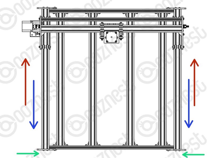 |
- Slide the X-Gantry to the back of the machine as far as it will go.
- Slightly loosen the 4 x M5-Button-Head-Bolt-12mm on each of the two front Y-End-Plates.
- Carefully slide the X-Gantry to the front of the machine as far as it will go.
- Re-tighten the M5-Button-Head-Bolt-12mm loosened in the green point above.
|
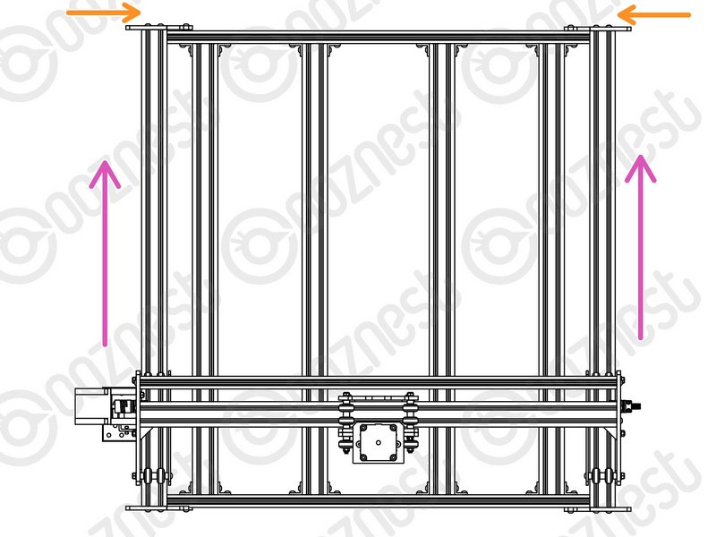 |
- Keep the machine at the front and slightly loosen the 4 x M5-Button-Head-Bolt-12mm on each of the two back Y-End-Plates.
- Carefully slide the X-Gantry to the back of the machine as far as it will go.
- Re-tighten the M5-Button-Head-Bolt-12mm loosened in the orange point above.
|
Slide the X-Gantry back and forth. It should run smoothly without binding.
| Image |
Instructions |
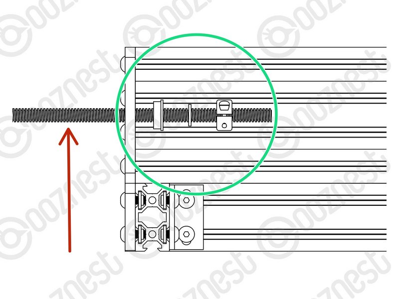 |
- Insert a Lead-Screw-Y through the large 16mm hole on the front right Y-End-Plate so it protrudes into the channel on Extrusion-F roughly 100mm.
- Slide onto Lead-Screw-Y a Flanged-Radial-Bearing -> Rubber-Bushing -> Clamping-Collar.
|
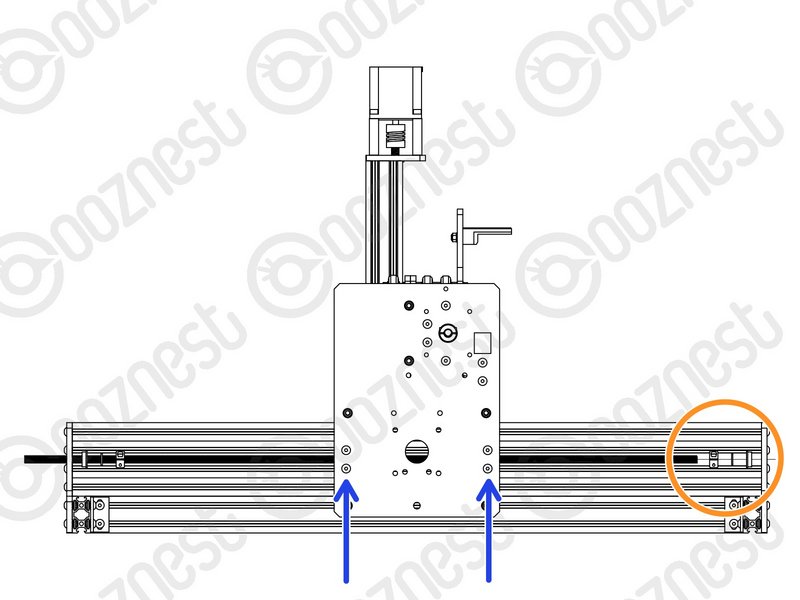 |
- Insert the Lead-Screw-Y further into the channel, and then thread it through both Nut-Blocks on the Y-Carriage-Right.
- The Nut-Blocks should be loose so their position can be adjusted to allow Lead-Screw-X to thread through.
- Once through the Nut-Blocks, slide onto Lead-Screw-Y a Clamping-Collar -> Rubber-Bushing -> Flanged-Radial-Bearing.
|
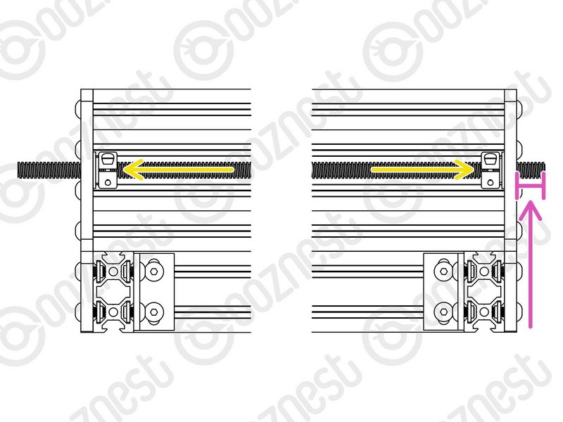 |
- Thread through Lead-Screw-Y further so it goes through the large 16mm hole on the back right Y-End-Plate. Adjust the Lead-Screw so there is 14mm protruding from the back right Y-End-Plate.
- Seat the Flanged-Radial-Bearings into the Y-End-Plates, slide the Rubber-Bushing against the Flanged-Radial-Bearings and finally slide the Clamping-Collars so they are against against the Rubber-Bushings. Slightly tighten the Clamping-Collars.
- Repeat all the above points for the left Y-End-Plates and Y-Carriage-Left.
|
Thrust-Bearings come in 3 parts. Thrust-Bearing-Housing-Washer, Thrust-Bearing-Caged-Roller and Thrust-Bearing-Shaft-Washer
The Thrust-Bearing-Housing-Washer and Thrust-Bearing-Shaft-Washer look exactly the same. They are not. The Thrust-Bearing-Shaft-Washer has a smaller internal diameter thus it will be tighter on the Lead-Screw.
We recommend adding a generous amount of bearing Lubricant to the grooved face of both washers.
| Image |
Instructions |
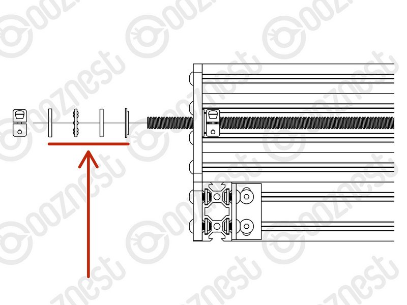 |
- On the Lead-Screw-Y protruding from the front right Y-End-Plate, slide on a Nylon-Shoulder-Washer -> Thrust-Bearing-Housing-Washer -> Thrust-Bearing-Caged-Roller -> Thrust-Bearing-Shaft-Washer
- The Nylon-Shoulder-Washer seats in the 16mm hole on the Y-End-Plate.
|
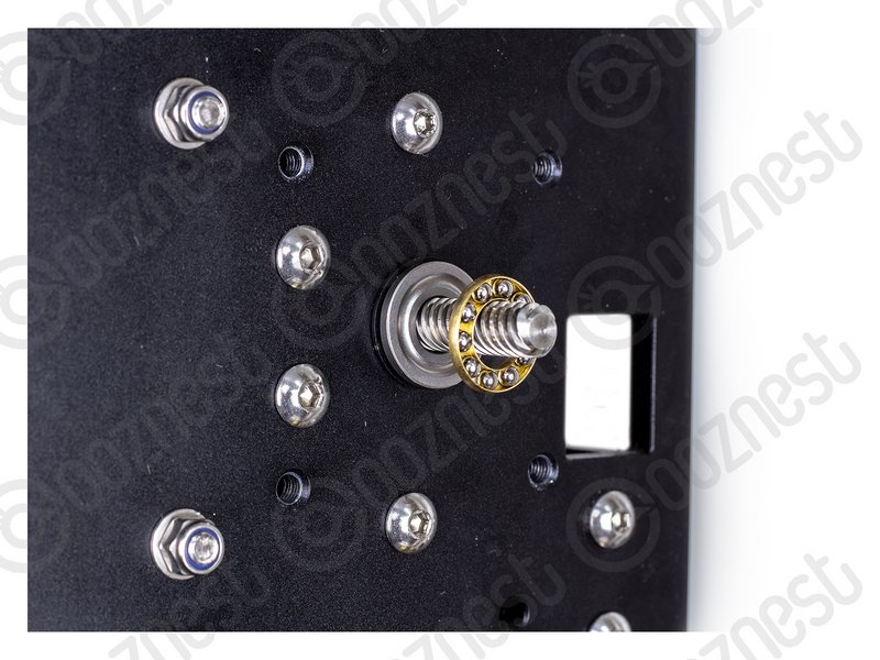 |
- The Thrust-Bearing-Caged-Roller seats in the grooves on the Thrust-Bearing washers. Same orientation as before.
|
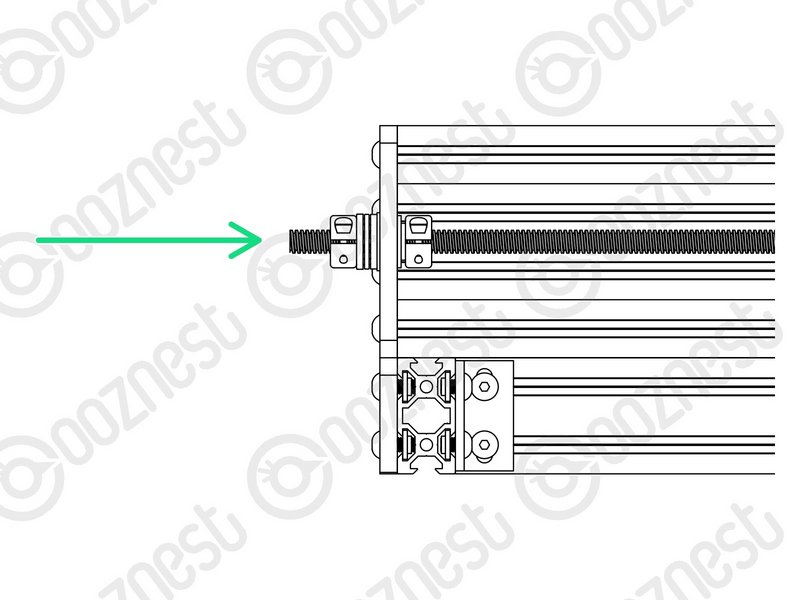 |
- Finally slide on a Clamping Collar. While pushing the Clamping-Collar against the Thrust-Bearing assembly, tighten the Clamping-Collar.
- Repeat all the above for the front left Y-End-Plate.
|
| Image |
Instructions |
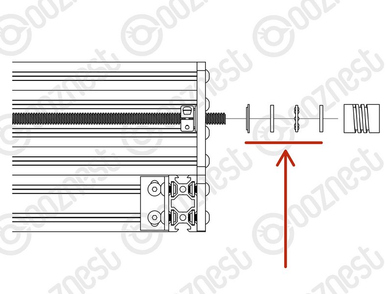 |
- On the Lead-Screw-Y protruding from the back right Y-End-Plate slide on a Nylon-Shoulder-Washer -> Thrust-Bearing-Housing-Washer -> Thrust-Bearing-Caged-Roller -> Thrust-Bearing-Shaft-Washer
- The Nylon-Shoulder-Washer seats in the 16mm hole on the Y-End-Plate.
|
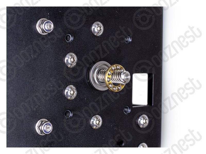 |
- The Thrust-Bearing-Caged-Roller seats in the grooves on the Thrust-Bearing washers. Same orientation as before.
|
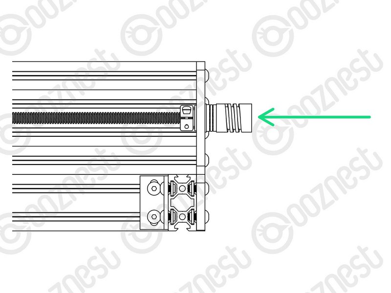 |
- Finally slide on a Flexible-Coupler. While pushing the Flexible-Coupler against the Thrust-Bearing assembly, tighten Flexible-Coupler
- On the Flexible-Coupler tighten the clamping bolt first and then the grub screw.
- Repeat all the above for the back left Y-End-Plate.
|
| Image |
Instructions |
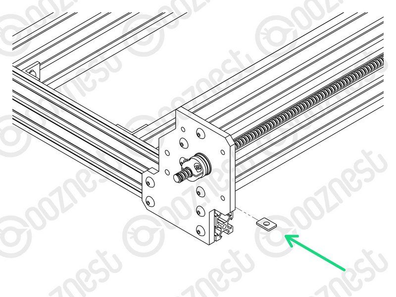 |
- At the front right corner of the machine, an Angle-Corner goes in the corner between Extrusion-A and Extrusion-F.
- First slide an M5-Tee-Nut into the top slot of Extrusion-A.
- The flat face of the M5-Tee-Nut should be facing upwards.
|
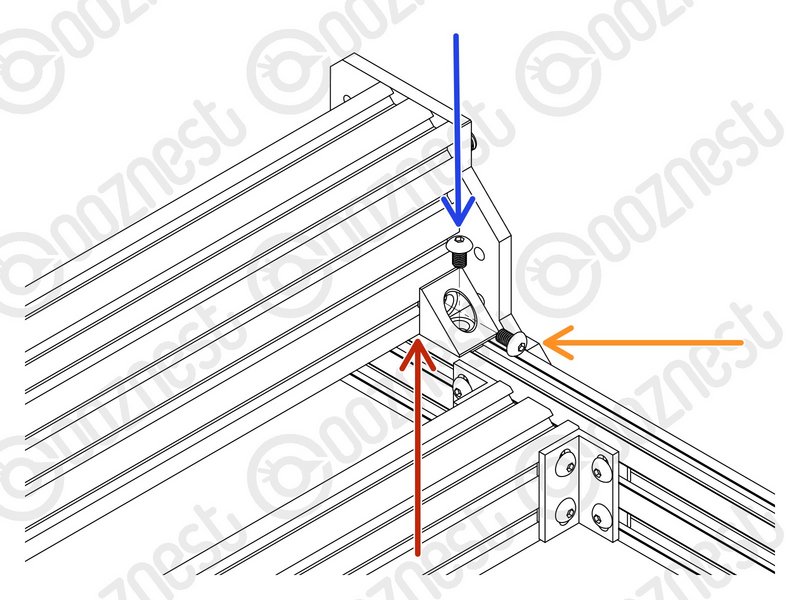 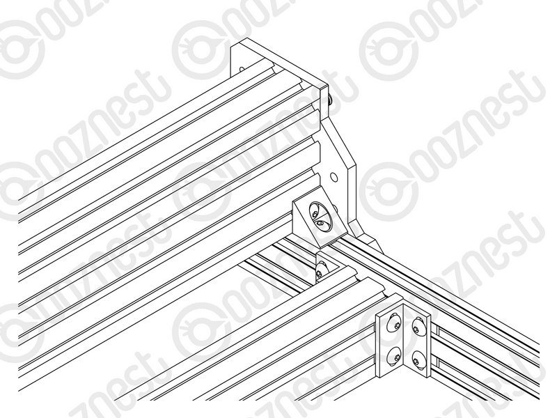 |
- Use a M5-Button-Head-Bolt-8mm and the previously inserted M5-Tee-Nut to attach it to Extrusion-A.
- To attach it to Extrusion-F, use a M5-Button-Head-Bolt-8mm and M5-Drop-In-Tee-Nut.
- M5-Drop-In-Tee-Nuts do not need to slide in from the end.
- They go in to the slot parallel, when the bolt engages they should spin perpendicular to the slot and bite into the underside of the slot.
|
| Image |
Instructions |
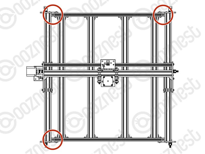 |
- Repeat the previous step for the other 3 corners.
|
Double-check the M5-Drop-In-Tee-Nuts are correctly engaged with Extrusion-F.
| Image |
Instructions |
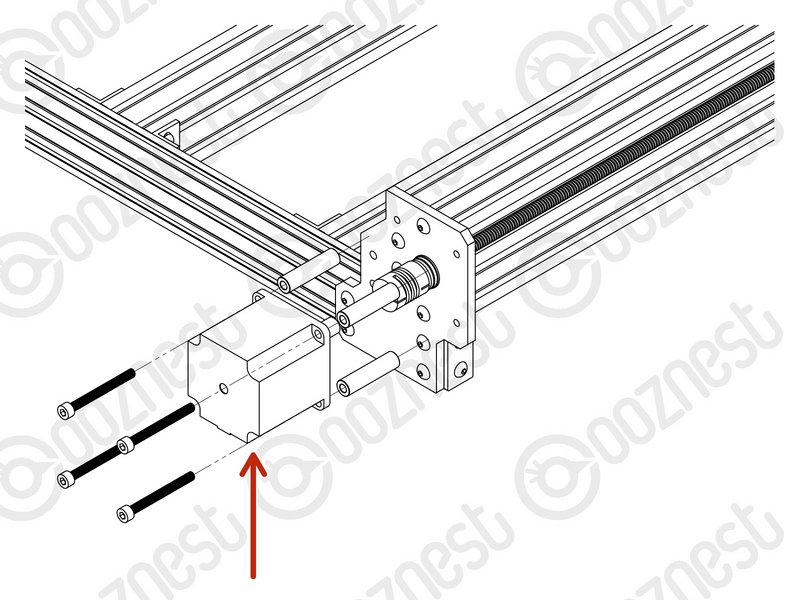 |
- Attach a Stepper-Motor to the threaded holes on the back left Y-End-Plate using 4 x M5-Cap-Head-Bolt-50mm and 4 x Aluminium-Spacer-40mms.
|
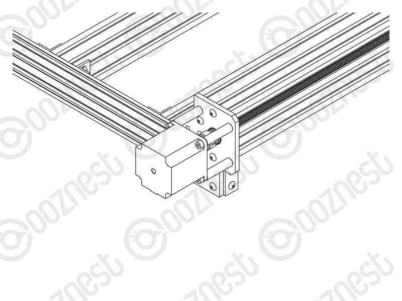 |
- Orient the Stepper-Motor so that the wire is facing down.
|
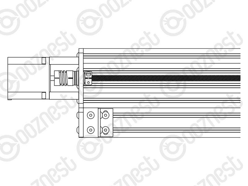 |
- The shaft of the Stepper-Motor goes into the Flexible-Coupler.
- On the Stepper-Motor side make sure the Flexible-Coupler grub screw is on the flat portion of the Stepper-Motor shaft.
- Once in position, tighten the clamping bolt first, then the grub screw.
|
The Lead-Screw side was tightened earlier in this guide.
| Image |
Instructions |
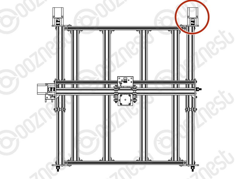 |
- Repeat the previous step for the right Y-Axis Stepper-Motor.
|
| Image |
Instructions |
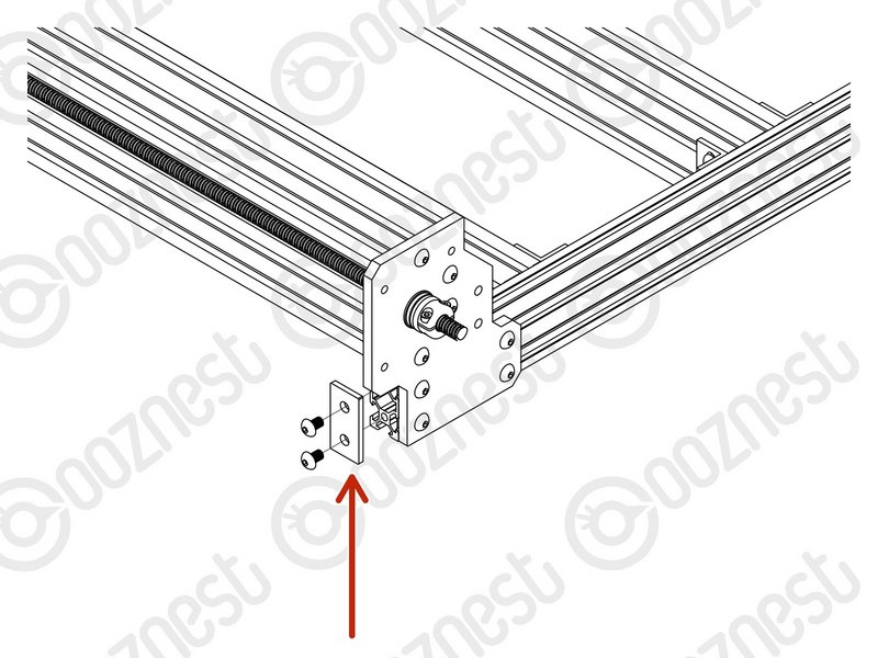 |
- Attach an End-Cap to the front left end of Extrusion-A using 2 x M5-Button-Head-Bolt-8mm.
|
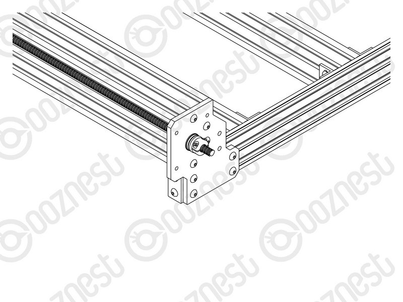 |
- Repeat this for the other 3 bare ends of the Extrusion-A's.
|
| Image |
Instructions |
 |
- Wow, what a difference. The machine can stay where it is now, we are going to be adding more stuff on!
- Guide Complete - Proceed to WorkBee Router Mount Assembly
|