You are going to need our Motor Wire and Limit Switch Cheat Sheet. We recommend printing it off!
For the below A Pozi #1 Screwdriver should be used. The best technique is to thread into the Limit-Switch a small amount, then back out. Then back in further, back out, so on so fourth until the Limit-Switch is secure.
Do not over tighten as you can shatter the switch. Make sure the Limit-Switch is orientated correctly.
| Image |
Instructions |
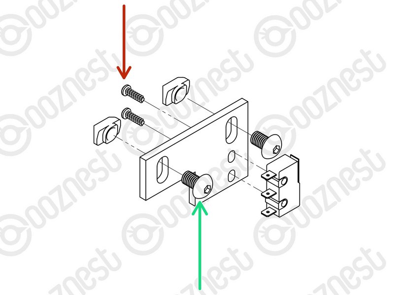 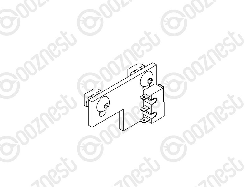 |
- Attach Limit-Switch-0 to the X-Limit-Switch-Mount using 2 x M3-Plastite-Screw-8mm.
- The M3-Plastite-Screw-8mm's go through the X-Limit-Switch-Mount first, then self thread into Limit-Switch-0.
- Insert 2 x M5-Button-Head-Bolt-8mm through the elongated holes on the X-Limit-Switch-Mount and slightly thread on 2 x M5-Drop-In-Tee-Nut.
|
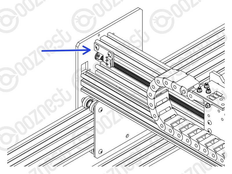 |
- Attach the X-Limit-Switch-Mount to the back of Extrusion-E. It should be at the left side if looking from the back. The X-Limit Switch-Mount should be up against the Y-Carriage.
- Make sure the M5-Drop-In-Tee-Nuts are engaged with the slots on Extrusion-E.
|
| Image |
Instructions |
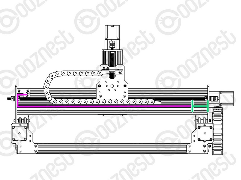 |
- With sharp scissors cut 50mm off one end of the Slot-Cover keeping the longer piece.
- The wire of Limit-Switch-0 runs inside the back top slot of Extrusion-B.
- Put the wire in this slot, and insert the Slot-Cover over it to hold it in place.
- There should be a 50mm gap of exposed slot on the opposite end of Extrusion-B.
|
For the below A Pozi #1 Screwdriver should be used. The best technique is to thread into the Limit-Switch a small amount, then back out. Then back in further, back out, so on so fourth until the Limit-Switch is secure.
Do not over tighten as you can shatter the switch. Make sure the Limit-Switch is orientated correctly.
This step uses the Limit-Switch-1 you inserted into Drag-Chain-Y in the previous guide. It should be sticking out the Fixed End of Drag-Chain-Y.
| Image |
Instructions |
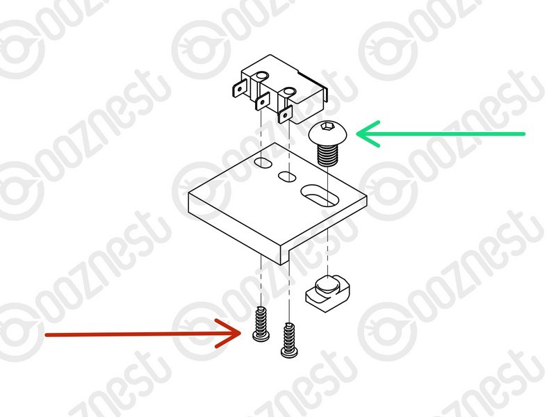 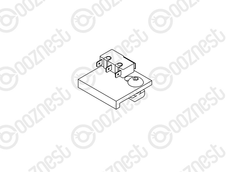 |
- Attach Limit-Switch-1 to the Y-Limit-Switch-Mount using 2 x M3-Plastite-Screw-8mm.
- The M3-Plastite-Screw-8mm's go through the Y-Limit-Switch-Mount first, then self thread into Limit-Switch-1.
- The best technique is to thread into Limit-Switch-1 a small amount, then back out. Then back in further, back out, so on so fourth until Limit-Switch-1 is secure.
- Do not over tighten as you can shatter the switch. Make sure Limit-Switch-1 is orientated correctly.
- Insert a M5-Button-Head-Bolt-8mm through the elongated hole on the Y-Limit-Switch-Mount and slightly thread on a M5-Drop-In-Tee-Nut.
|
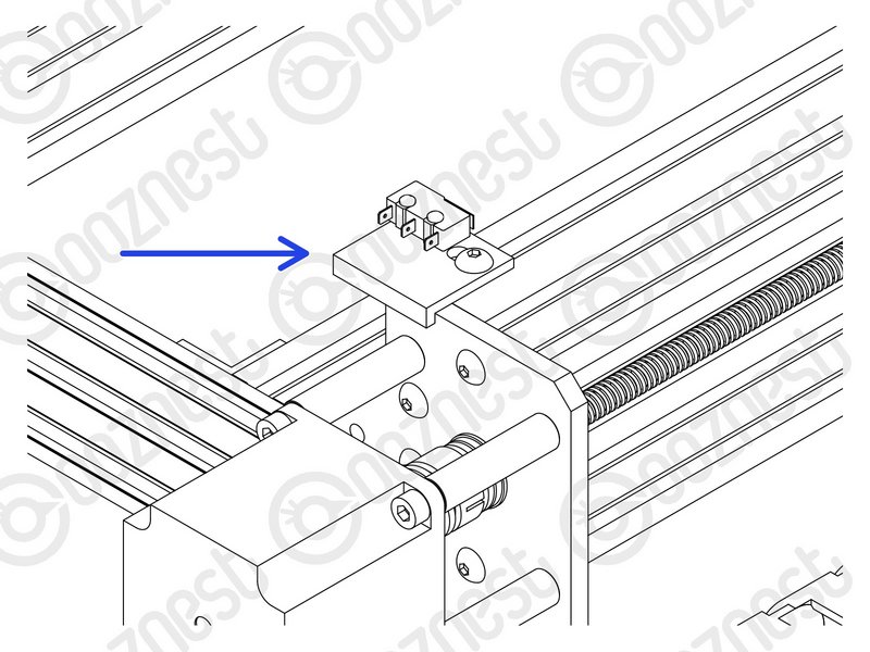 |
- Attach the Y-Limit-Switch-Mount to the back of Extrusion-F. It should be on the right Extrusion-F if looking from the back. The Y-Limit Switch Mount should locate on the corner of Extrusion-F.
- Make sure the M5-Drop-In-Tee-Nut is engaged with the slot on Extrusion-F.
|
| Image |
Instructions |
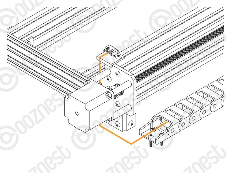 |
- The wire of Limit-Switch-1 should follow the direction shown in Image 1.
|
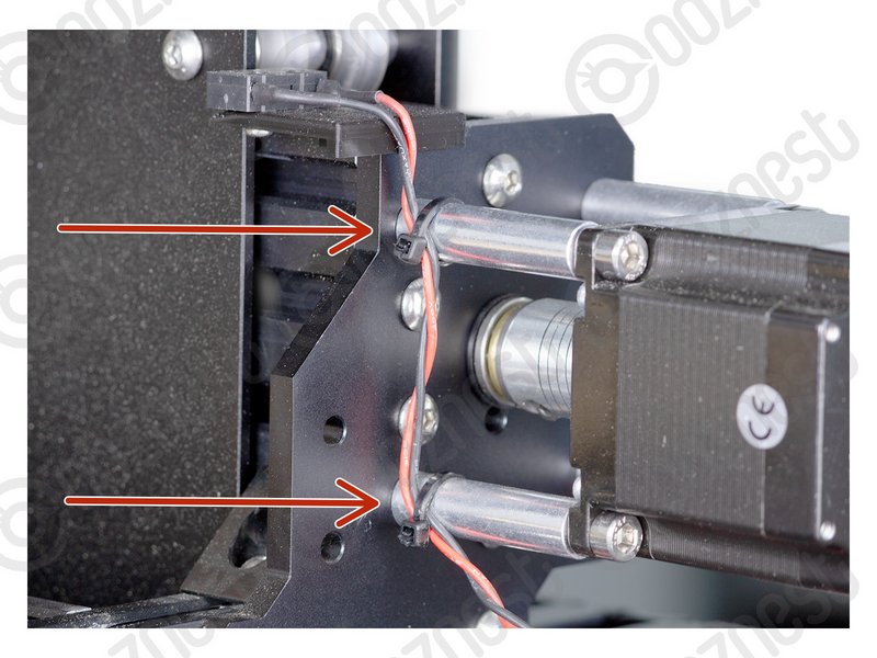 |
- Use 2 x Cable-Tie-Small on the Aluminium-Spacer-40mms to keep it in place as shown in Image 2.
- Any slack in the wire of Limit-Switch-1 should be pulled out of the opposite end of the Drag-Chain-Y.
- Double check your wire routing matches Image 2.
|
| Image |
Instructions |
 |
|