The back is the side with the counterbores.
| Image |
Instructions |
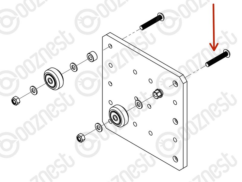 |
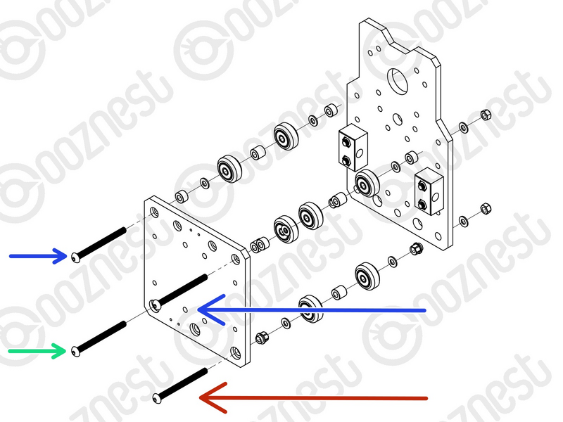
- Assemble the top right Solid-Wheel set first. Insert a M5-Button-Head-Bolt-30mm through the Z-Plate from the back.
- On to the bolt add an Eccentric-Spacer-6mm. (Rounded portion into the Z-Plate)
- Then add a Precision-Shim -> Solid-Wheel -> Precision-Shim
- Finally add a M5-Nyloc-Nut. This can be tightened. Ensure that the Solid-Wheel still rotates freely.
|
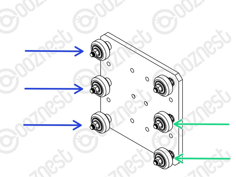 |
- Repeat the above for the other 2 x Solid-Wheel set on the right row.
- Repeat for the 3 x Solid-Wheel sets on the left row, but use a Aluminium-Spacer-6mm instead of each Eccentric-Spacer-6mm.
|
| Image |
Instructions |
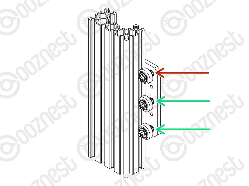 |
- On the hexagonal portion of the Eccentric-Spacer-6mm, there will be a face that is marked with ‘6mm’.
- Using a 8mm spanner, rotate each Eccentric-Spacer-6mm so that this face is facing right. (Doing this maximises the gap between the left and right row of Solid-Wheels)
|
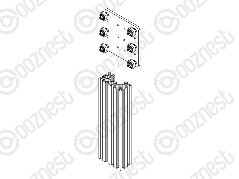 |
- Insert Extrusion-D in-between the two rows of wheels. Turn the assembly on to it's left side so Extrusion-D is sitting on the left row of Solid-Wheels.
- Starting with the top right Solid-Wheel. Rotate the Eccentric-Spacer-6mm until there is a small amount of friction between the Solid-Wheel and Extrusion-D
- Repeat for the bottom right Solid-Wheel. Then repeat for the middle right Solid-Wheel.
- Slide Extrusion-D back and forth. This should require a small amount of force, and all Solid-Wheels should spin.
- Check there is no wobbling of Extrusion-D. Once happy, double-check the tightness of the M5-Nyloc Nuts and remove Extrusion-D.
- Try to get all the Solid-Wheels touching Extrusion-D as best as possible. If not, it is not a problem, we will check the Eccentric-Spacers-6mms again once the machine is built.
|
| Image |
Instructions |
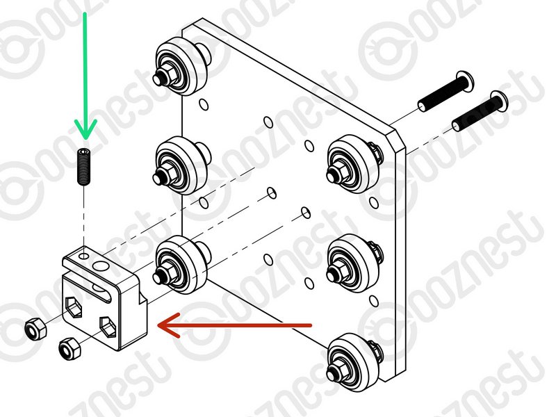 |
- Attach the Z-Axis-Nut-Block to the Z-Plate using 2 x M5-Button-Head-Bolt-25mm & 2 x M5-Nyloc-Nuts.
|
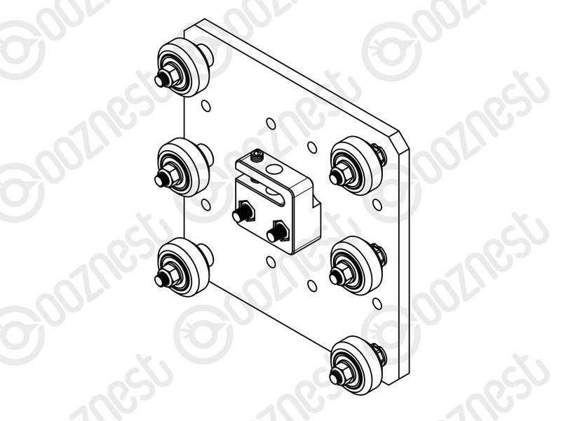 |
- In the Z-Axis-Nut-Block bag there is a set screw. Screw it into the top of the Z-Axis-Nut-Block until it just touches the surface on the opposite side of the gap.
|
The set screw will later be used to remove any backlash from the Z-Axis.
Discard the nut left in the bag with the Z-Axis-Nut-Block.
Moving forward this will be known as the Z-Plate-Assembly
| Image |
Instructions |
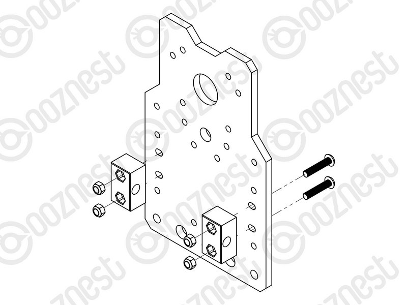 |
- Attach 2 x Nut-Blocks to the X-Plate-Back using 2 x M5-Button-Head-Bolt-25mm & 2 x M5-Nyloc-Nuts.
|
Keep these bolts loose so the Nut-Blocks can still move side to side.
The back is the side without the counterbores.
The Limit-Switches are located in the 'Wires' box. They have red/black wires attached to them. The wires are not shown in the assembly picture. Look at the Cheat Sheet to find the correct Limit-Switch.
| Image |
Instructions |
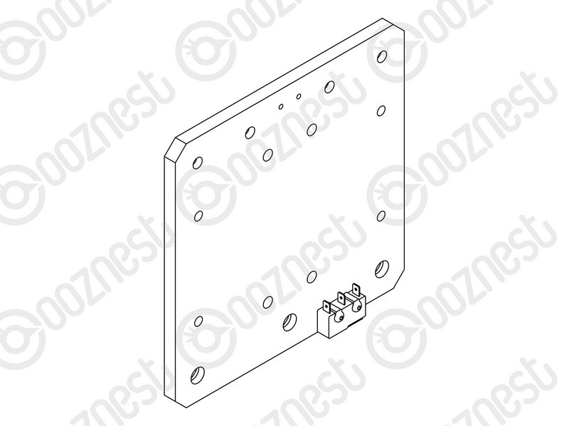 |
- Attach the Limit-Switch-2 to the threaded holes on the back of the X-Plate-Front using 2 x M2.5-Button-Head-Bolt-10mm.
|
The wire will be sorted later in the manual.
| Image |
Instructions |
 |
- Assemble the bottom right Solid-Wheel set first. Insert a M5-Button-Head-Bolt-60mm through the X-Plate-Front from the front.
|
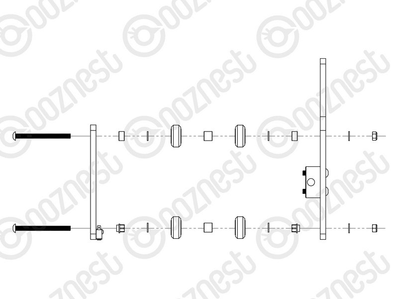 |
- On to the bolt add an Eccentric-Spacer-6mm. (Rounded portion into the X-Plate-Front)
- Then add a Precision-Shim -> Solid-Wheel -> Aluminium-Spacer-9mm -> Solid-Wheel -> Precision-Shim
- Add an Eccentric-Spacer-6mm then the X-Plate-Back. (Rounded portion of the Eccentric-Spacer-6mm goes into the X-Plate-Back)
- On the outside of the X-Plate-Back add onto the bolt a Precision Shim then a M5-Nyloc-Nut. Only slightly thread on the M5-Nyloc-Nut.
|
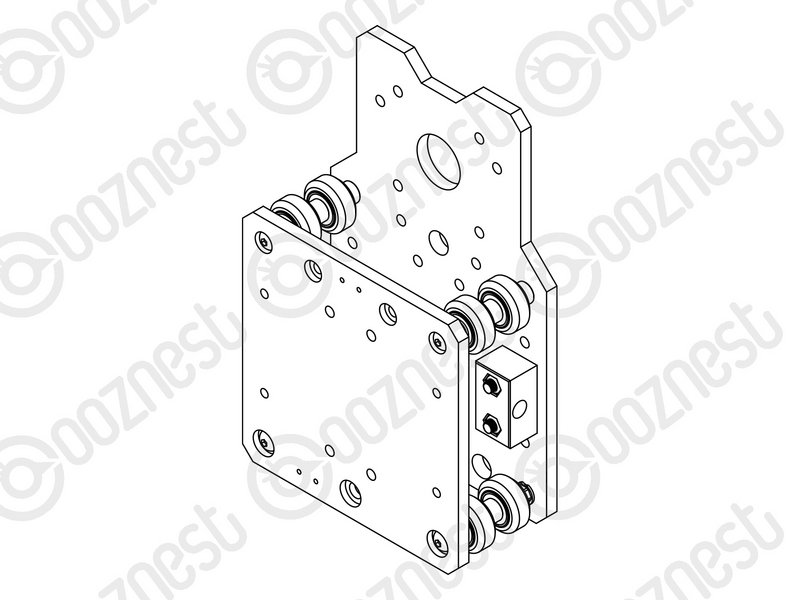 |
- Repeat the above for the other Solid-Wheel set on the bottom row.
- Repeat for the 2 x Solid-Wheel sets on the top row, but use a Aluminium-Spacer-6mm instead of each Eccentric-Spacer-6mm.
- The M5-Nyloc-Nuts can now be tightened. Ensure that each Solid-Wheel still rotates freely.
|
| Image |
Instructions |
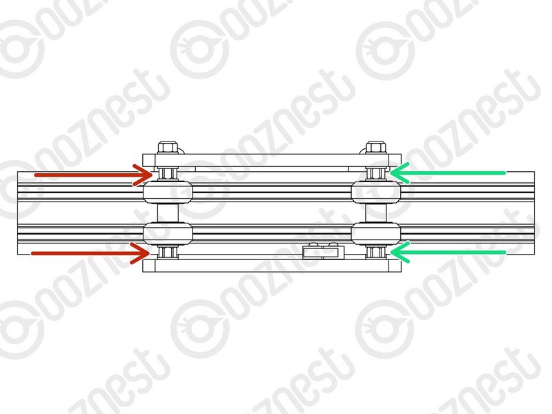 |
- On the hexagonal portion of the Eccentric-Spacer-6mm, there will be a face that is marked with ‘6mm’.
- Using a 8mm spanner, rotate each Eccentric-Spacer-6mm so that this face is facing downwards. (Doing this maximises the gap between the top and bottom row of Solid-Wheels)
|
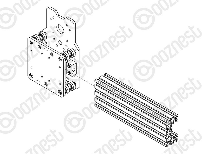 |
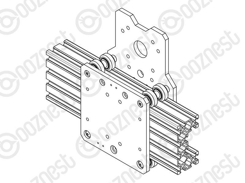
- Insert Extrusion-D in-between the two rows of wheels. Turn the assembly upside down so Extrusion-D is sitting on the top row of Solid-Wheels.
- Rotate both Eccentric-Spacer-6mms on one set of Solid-Wheels until there is a small amount of friction between the Solid-Wheels and Extrusion-D
- Repeat for the other set of Solid-Wheels.
- Slide Extrusion-D back and forth. This should require a small amount of force, and all Solid-Wheels should spin.
- Check there is no wobbling of Extrusion-D. Once happy, double-check the tightness of the M5-Nyloc Nuts and remove Extrusion-D.
|
 |
- Try to get all the Solid-Wheels touching Extrusion-D as best as possible. If not, it is not a problem, we will check the Eccentric-Spacers-6mms again once the machine is built.
|
| Image |
Instructions |
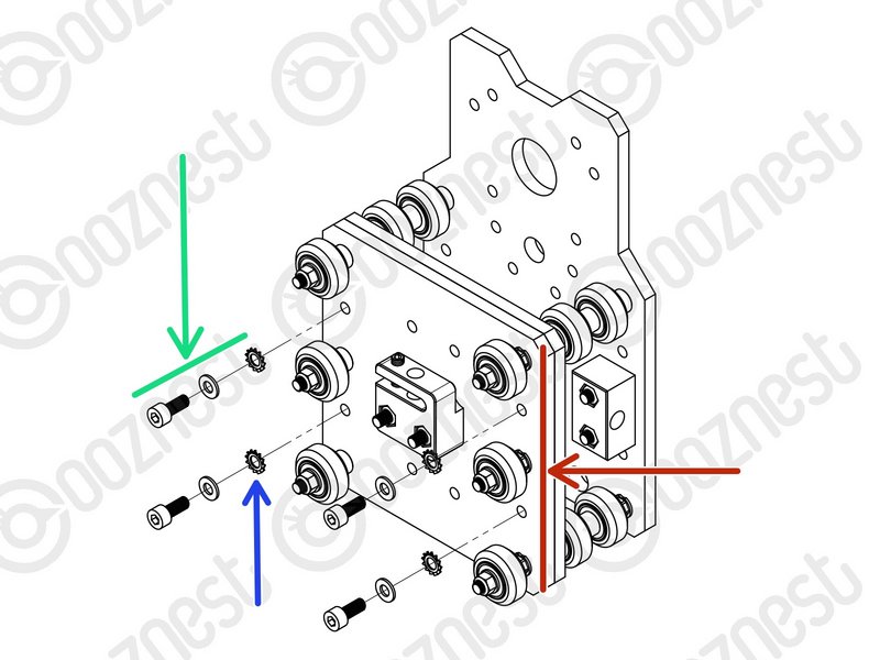 |
- Mate the Z-Plate-Assembly to the X-Plate-Front.
- The Z-Plate-Assembly should be orientated with the Eccentric-Spacer-6mms on the right side.
- Secure using 4 x M5-Cap-Head-Bolt-12mm, 4 x Precision Shim and 4 x Locking-Washer.
- The Locking-Washer should go in-between the Precision-Shim and Z-Plate.
|
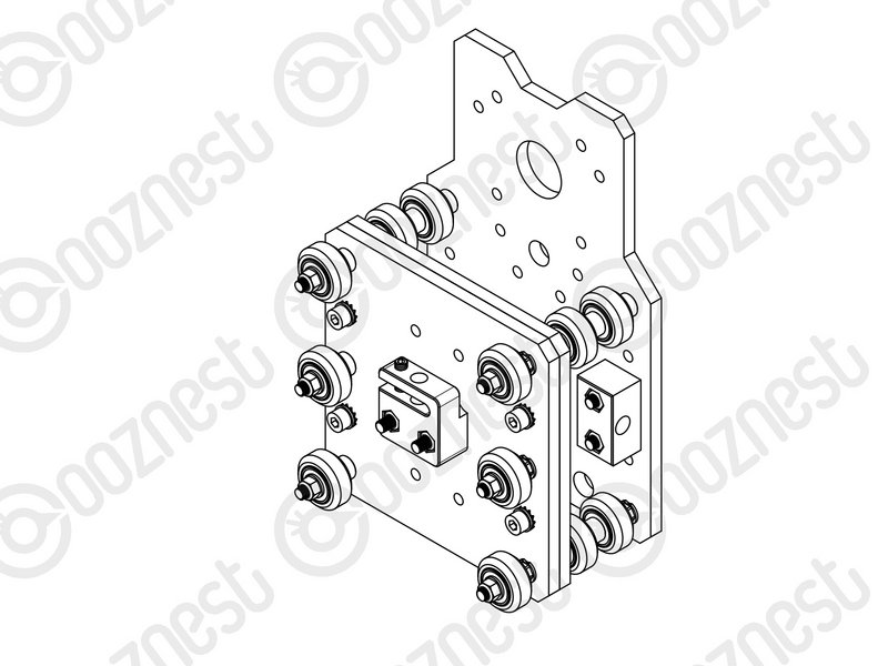 |
- Make sure the Z-Plate-Assembly is square to the X-Carriage-Assembly.
- Do not over-tighten the M5-Cap-Head-Bolt. If over-tightened it will reduce the effectiveness of the Locking-Washer.
|
| Image |
Instructions |
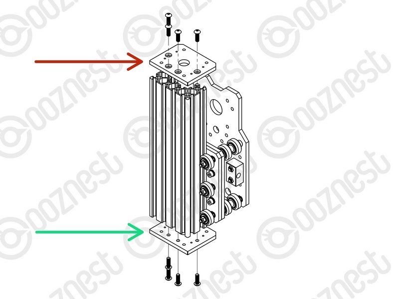 |
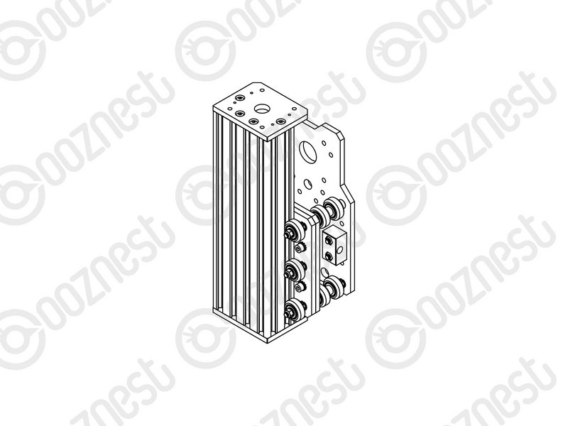
- Slide Extrusion-D through the Solid-Wheels on the Z-Plate-Assembly.
- Attach a Z-End-Plate to the top of Extrusion-D using 4 x M5-Button-Head-Bolt-16mm.
|
 |
|
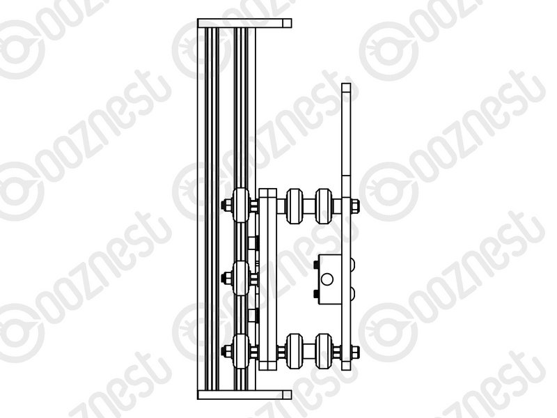 |
- Attach a Z-End-Plate to the bottom of Extrusion-D using 4 x M5-Button-Head-Bolt-16mm.
- Tighten the bolts fully, and then loosen by a single full turn.
- The reason for this will become clear later.
|
| Image |
Instructions |
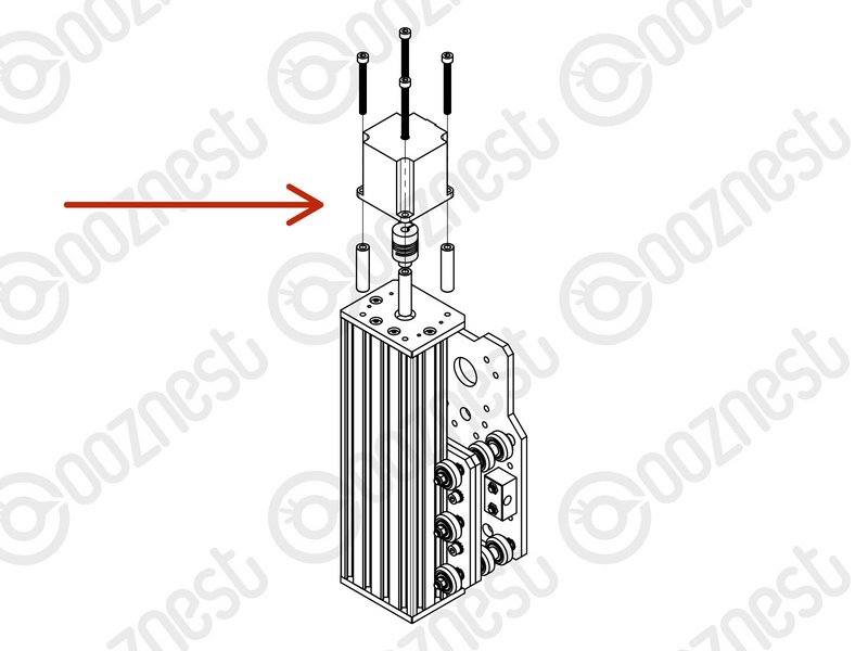 |
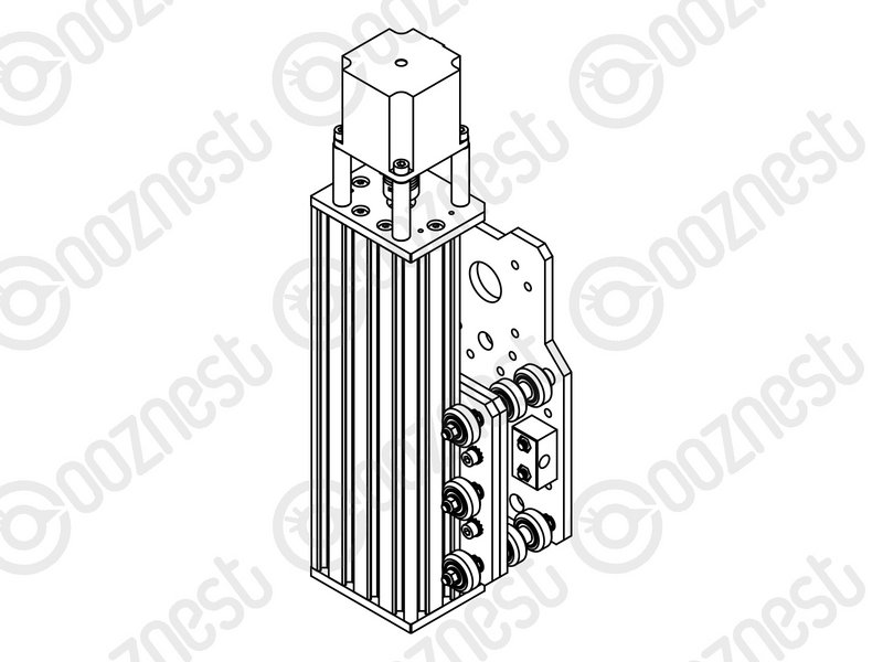
- Slide the 1/4” side (the side with the smallest hole) of the Flexible-Coupler onto the shaft of the Stepper-Motor. Don’t tighten it down at this point.
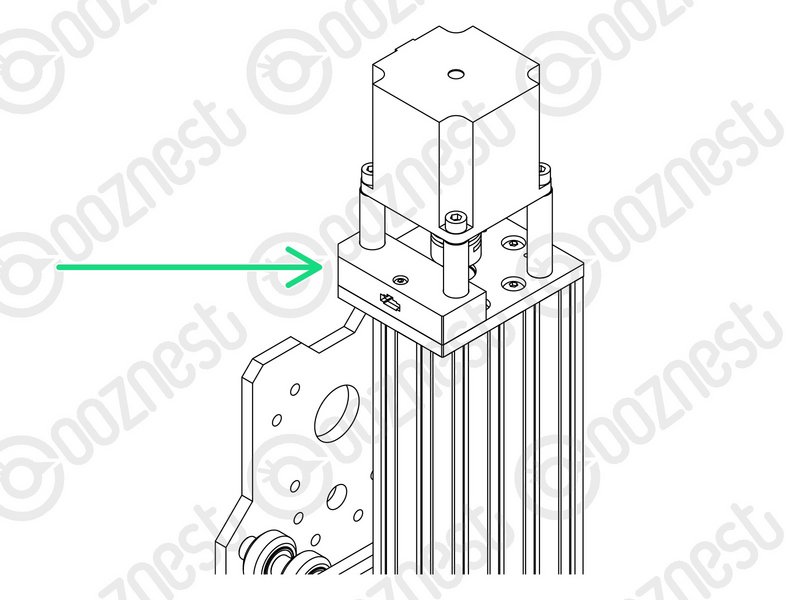
- Attach the Stepper-Motor to the threaded holes on the top Z-End-Plate using 4 x M5-Cap-Head-Bolt-50mm and 4 x Aluminium-Spacer-40mms.
|
 |
- Orient the Stepper-Motor so that the wire is towards the back of the X-Carriage-Assembly.
|
 |
|
| Image |
Instructions |
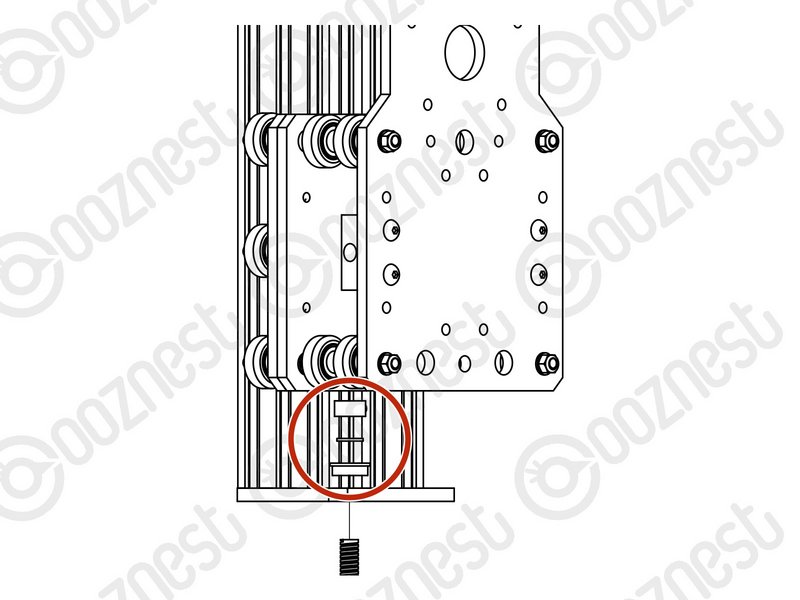 |
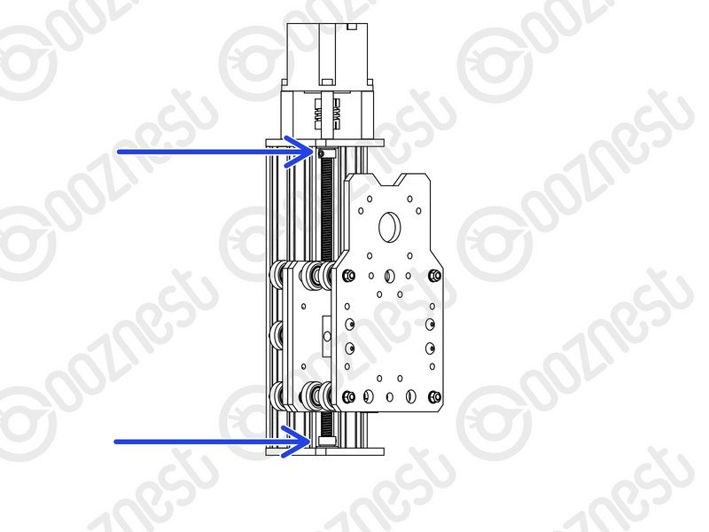
- Slide the Lead-Screw-Z through the bottom Z-End-Plate. Then slide on a Flanged-Radial-Bearing (facing downwards) -> Bearing-Shim -> Lock-Collar.
|
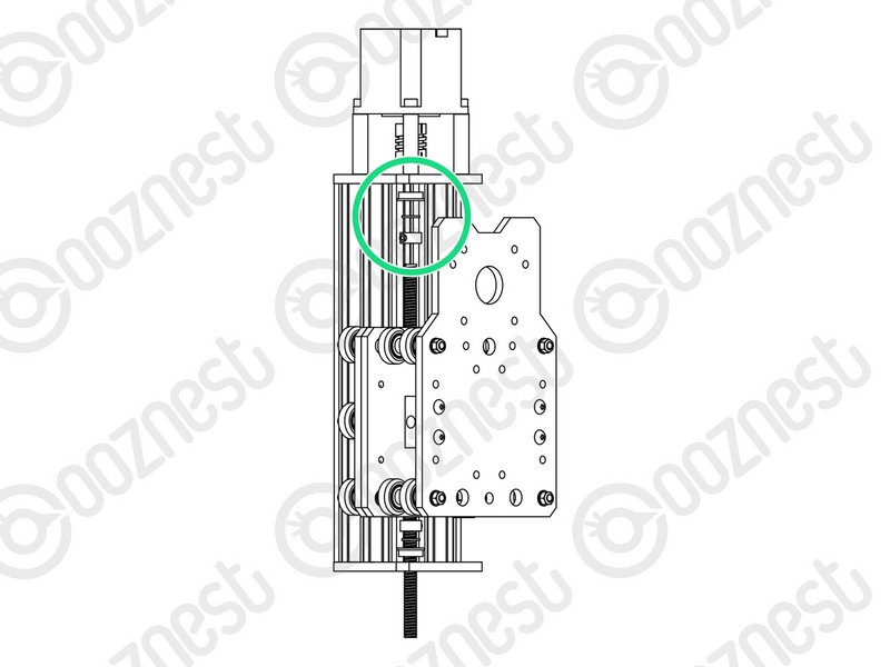 |
- Thread the Lead-Screw-Z through the Z-Axis-Nut-Block. Then slide on a Lock-Collar -> Bearing-Shim -> Flanged-Radial-Bearing (facing upwards).
|
 |
- Continue threading through the Lead-Screw-Z until it is touching the Stepper-Motor shaft.
- Position the Flexible-Coupler so it is half on the Lead-Screw-Z and half on the Stepper-Motor shaft.
- On the Stepper-Motor side make sure the Flexible-Coupler grub screw is on the flat portion of the Stepper-Motor shaft. Once in position, on both sides tighten the clamping bolts first, then the grub screws.
- Top & Bottom, slide the Flanged-Radial-Bearings along the Lead-Screw-Z until they seat fully in the Z-End-Plates.
- Slide the Bearing-Shim against the Flanged-Radial-Bearing, and finally slide the Lock-Collar so it is firmly against the Bearing-Shim. Lock each Lock-Collar in place using the grub screw on the side.
|
Locate the four bottom M5-Button-Head-Bolt-16mm that were loose from Step 9. These can now be fully tightened. This will remove any play that may be present.
| Image |
Instructions |
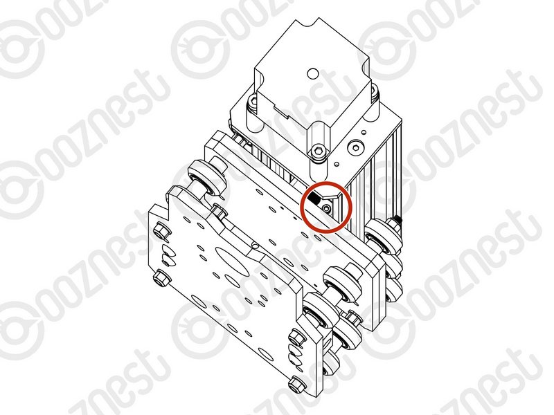 |
- Firmly hold the Assembly, and check for any up and down play in Extrusion-D.
- If there is any, this is due to backlash in the Z-Axis-Nut-Block.
- The set screw which was inserted in Step 3 into the Z-Axis-Nut-Block can be tightened to remove backlash.
|
Do not over tighten this, as it can make the Lead-Screw-Z difficult to turn. You can test this by rotating the Flexible-Coupler by hand.
It should require a small to medium amount of force. This will need to be checked once the router is attached, and periodically checked when in use.
| Image |
Instructions |
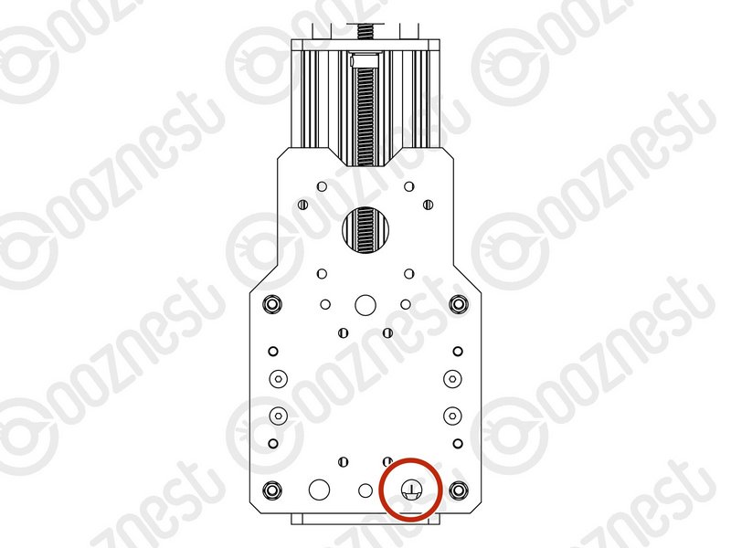 |
- Feed the wire of Limit-Switch-2 attached in Step 5 through the hole opposite on the X-Plate-Back.
|
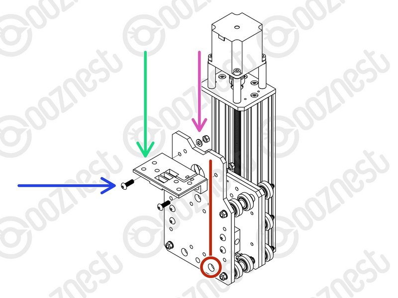 |
- A Drag-Chain-Mount needs to be attached to the X-Plate-Back.
- Insert 2 x M5-Button-Head-Bolt-16mms through the Drag-Chain-Mount.
|
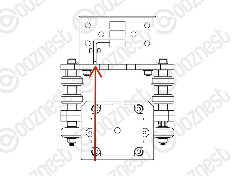 |
- Notice on the back of the Drag-Chain-Mount there is a slot. The Limit-Switch-2 wire goes up the X-Plate-Back and through this slot.
- Put the Drag-Chain-Mount against the X-Plate-Back with the Limit-Switch-2 wire in this slot.
- Then add a Precision-Shim and M5-Nyloc-Nut on the opposite side of the X-Plate-Back.
- Tighten the Drag-Chain-Mount against the X-Plate-Back
|
| Image |
Instructions |
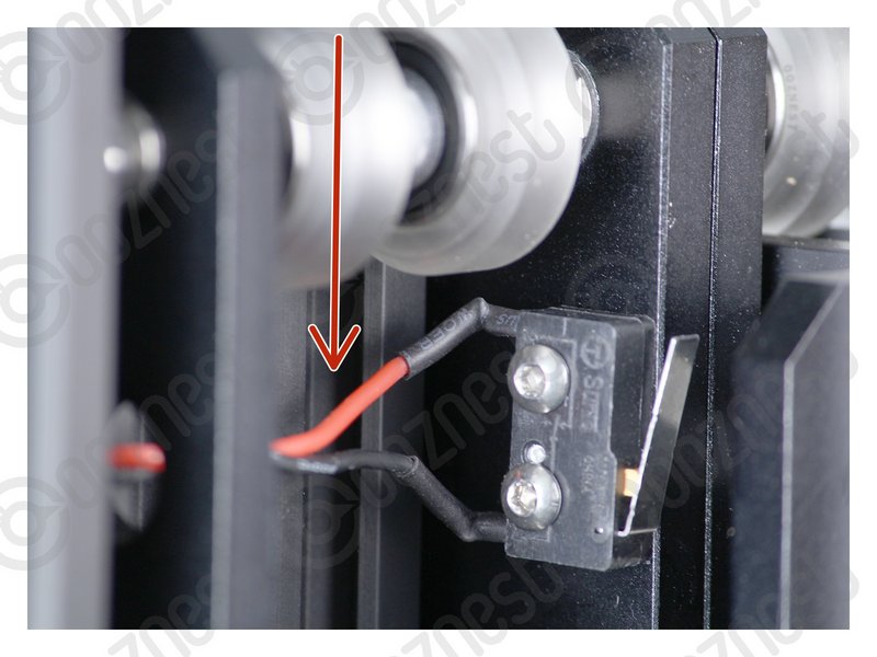 |
- Pull the Limit-Switch-2 Wire taut all the way from the switch to the Drag-Chain-Mount.
|
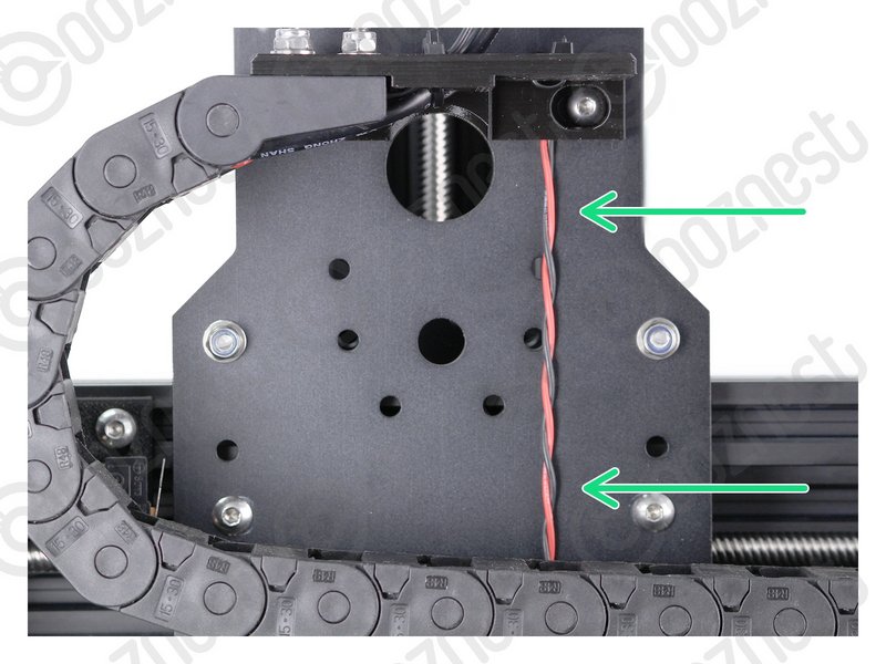 |
- This shows it taut up the back of the X-Plate-Back.
|
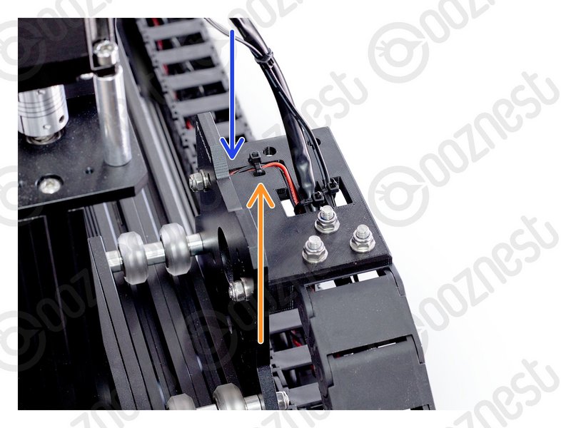 |
- This shows it inside the slot on the Drag-Chain-Mount.
- Make sure it is taut the whole way.
- Use a small cable tie to secure it to the Drag-Chain-Mount.
|
Make sure your Limit-Switch-2 Wire looks exactly like the images.
| Image |
Instructions |
 |
- Clear the table, you are going to need room. Keep this X-Carriage with you.
- Guide Complete - Proceed to 2.4 X-Gantry Assembly
|