Avoid connecting the Controller via USB when you do not need to. (Except when instructed to in the guides)
Always unplug the WorkBee Power Supply before connecting the USB Cable.
If you do not loose connection below, stop and Contact Us.
| Image |
Instructions |
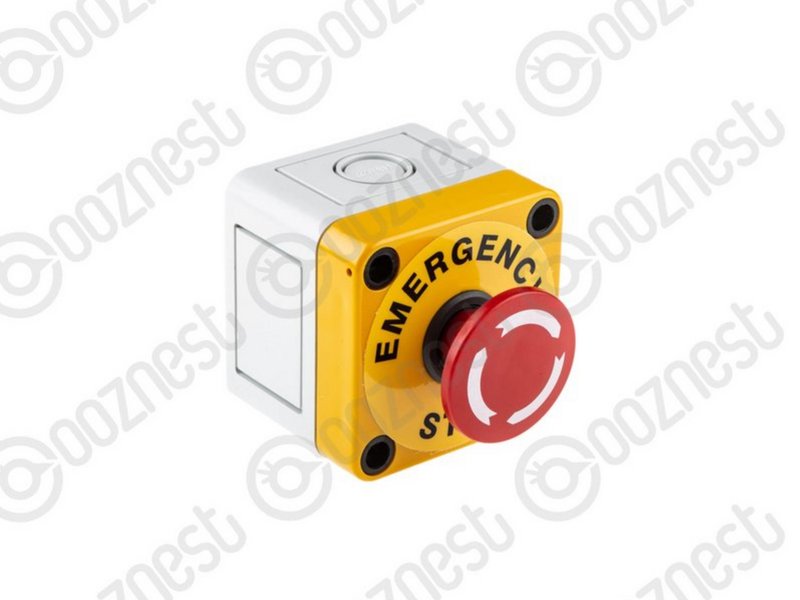 |
- The Emergency Stop has been pre-tested by Ooznest. But you should test it again.
- First insure the machine is switched on, and have WorkBee Control open on your web browser.
- Press the Emergency Stop.
- You should loose connection to WorkBee Control.
- If you do not loose connection make sure the USB Cable is not plugged in.
- With the connection lost, unlatch the Emergency Stop.
- After a few seconds WorkBee Control should reconnect.
|
| Image |
Instructions |
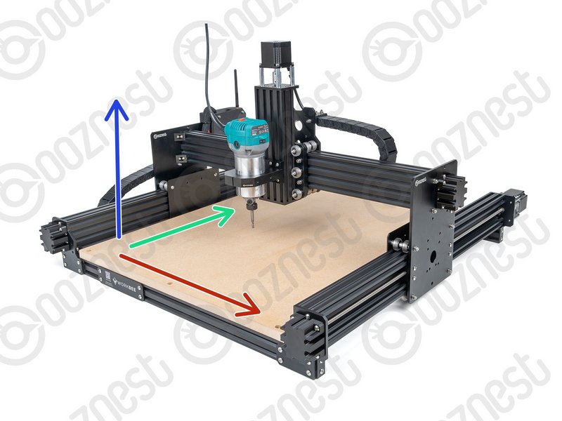 |
- If looking at the machine from the front the axis motion is:
- The X-Axis is positive towards the right.
- The Y-Axis is positive towards the back.
- The Z-Axis is positive going up.
|
| Image |
Instructions |
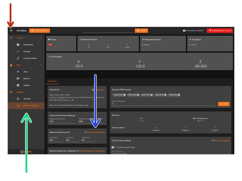 |
- In WorkBee Control open the Navigation Menu
- Under 'Settings', press 'Machine Specific'
- Under the Panel called 'Machine Working Area' press 'Reset Working Area'
|
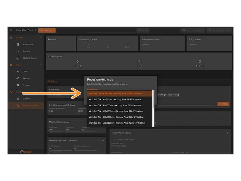 |
- Under the 'WorkBee Model' dropdown select your machine size.
- Yours is a Z1+ Model
- Confirm by pressing 'Yes'
- The machine is now configured. No restart required.
|
It is normal for there to be a delay between pressing the limit switch and the status being updated. Please do not be concerned, the board will stop the motor instantaneously.
| Image |
Instructions |
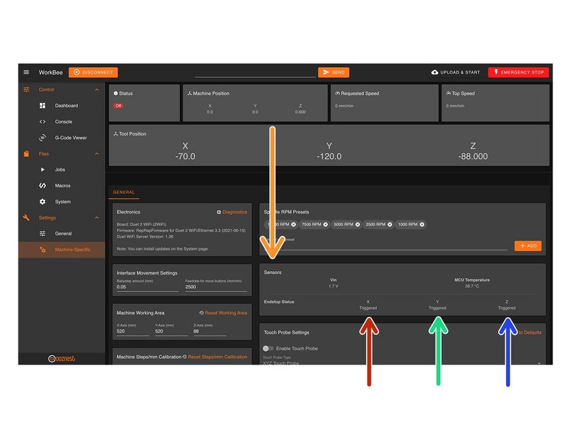 |
- On the same page, under the Panel called 'Sensors' we can test the Limit Switches.
- Activate the X-Axis limit switch with your finger and hold.
- The Endstop Status should change to 'Triggered'
- Repeat this procedure for the Y-Axis Limit Switch.
- Repeat this procedure for the Z-Axis Limit Switch.
|
If any do not behave as intended do not proceed with this guide, please Contact Us.
| Image |
Instructions |
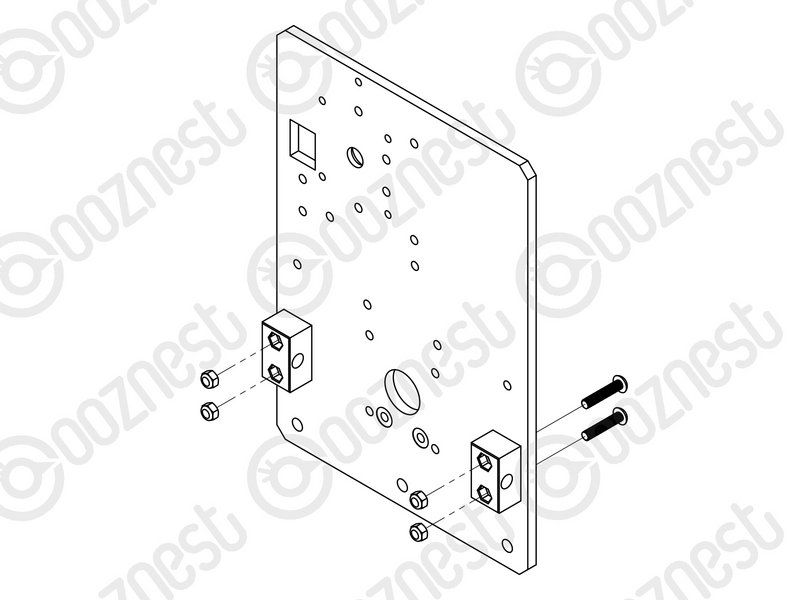 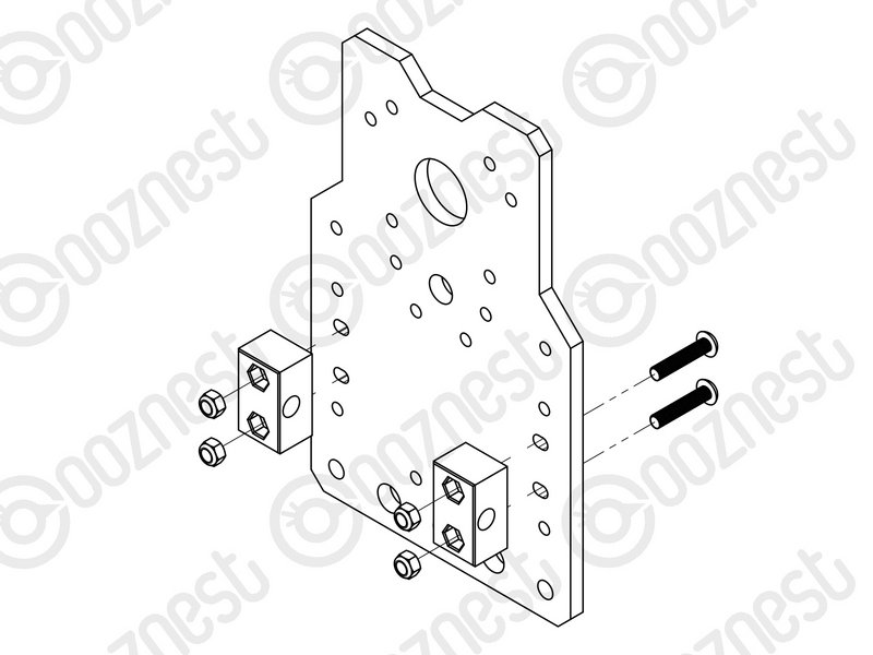 |
- At this point in time, the Nut Blocks on X & Y-Axis Carriages should be loose.
|
Do not over tighten the nut blocks, they will need to be undone shortly.
If any of the points below do not behave as explained do not proceed with this guide, please Contact Us.
| Image |
Instructions |
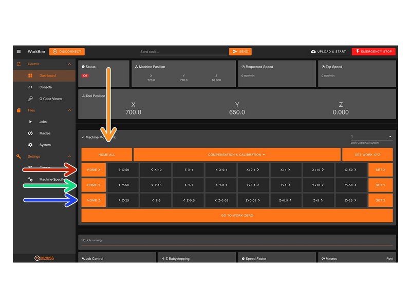 |
- When the machine homes, it will raise the Z-Axis, and then move the X and Y-Axis to the far right-hand corner.
- Press Home Z. The Z-Axis should raise upwards, bounce once on the limit switch, and then stop.
- Press Home X. The Z-Axis should home like the previous. The X-Axis should then move towards the right, bounce once on the limit switch, and then stop.
- Press Home Y. The Z-Axis should home like previous. The Y-Axis should then move towards the back, bounce once on the limit switch, and then stop.
- Press Home All. The Z-Axis should home like previous. Then the X and Y-Axis should home like previous.
|
If at any point below you loose power to motors and need to re-lock the motors, go to Control > Console and send the command 'M17'
| Image |
Instructions |
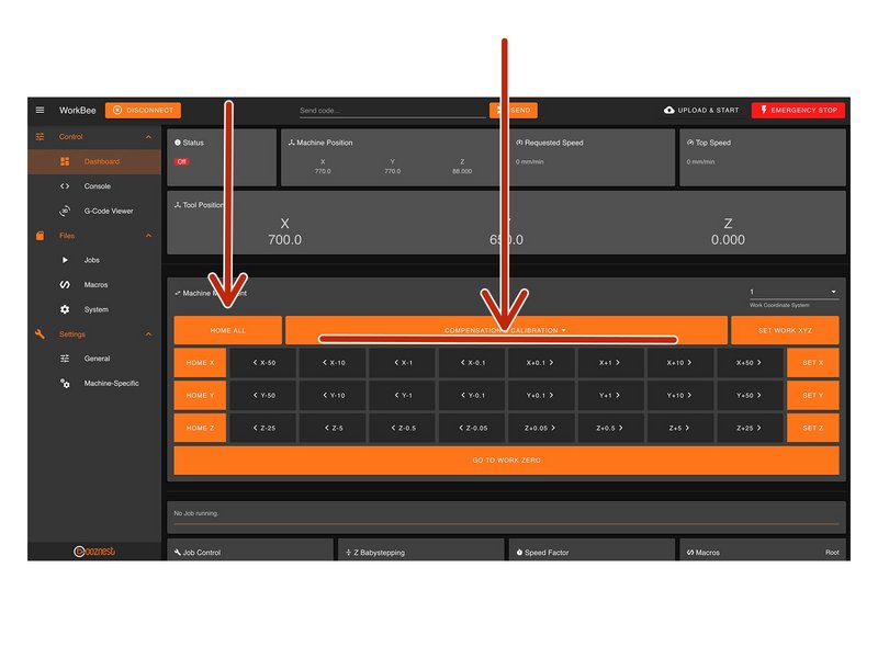 |
- Home the machine and use the jog buttons to move the machine roughly into the middle of the working area in X & Y.
- Leave the machine powered on so the Stepper-Motors stay locked.
- Loosen all the Nut-Blocks on the X & Y-Carriages.
- Loosen the Clamping-Collars that are on the inside channel of Extrusion-E/F on the X & Y Axes.
|
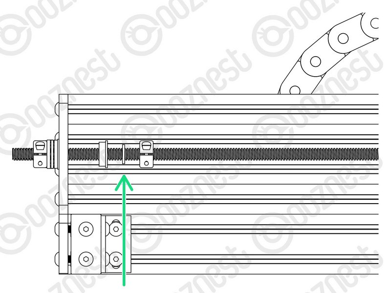 |
- Move the Rubber-Bushings & Clamping-Collars away from the plates.
|
Leave the machine powered on so the Stepper-Motors stay locked.
If at any point below you loose power to motors and need to re-lock the motors, go to Control > Console and send the command 'M17'
| Image |
Instructions |
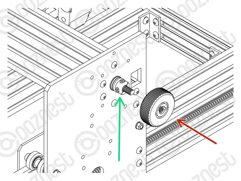 |
- Starting with the X-Axis, thread on the Tensioning-Knob until it is up against the Clamping-Collar.
- Then loosen the same Clamping-Collar.
- Turn the Tensioning-Knob clockwise, you will feel the Lead-Screw tension build.
- Keep turning until the Stepper-Motor clicks over.
- Keep turning, just before the point that the Stepper-Motor clicks over again is the correct amount of tension for the Lead-Screw.
- While at this point of tension, tighten the Clamping-Collar that is next to the Tensioning-Knob.
- Remove the Tensioning-Knob.
- Repeat all the above for both Lead-Screws on the Y-Axis.
|
If at any point below you loose power to motors and need to re-lock the motors, go to Control > Console and send the command 'M17'
| Image |
Instructions |
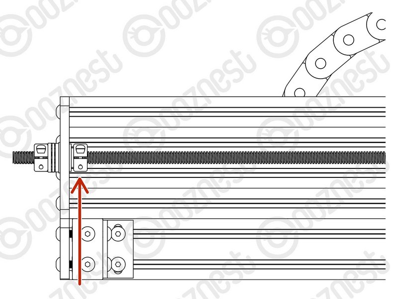 |
- Once all 3 Lead-Screws are tensioned, put back the Flanged-Radial-Bearings, Rubber-Bushings, and Clamping-Collars that are on the inside channel of Extrusion-E/F on the X & Y Axes.
- The Clamping-Collars only need to be pushed lightly up against the Rubber-Bushings & Flanged-Radial-Bearings. Tighten the Clamping-Collars.
|
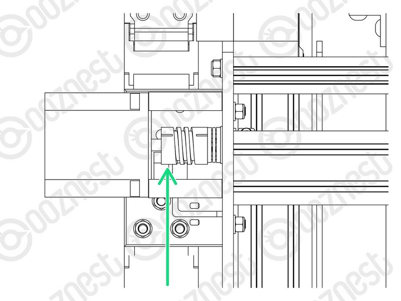 |
- On the Stepper-Motor side of the X & Y-Axis Flexible-Couplers completely loosen the grub screws and clamping bolts.
- Then completely tighten the same grub screws and clamping bolts.
- Tighten all the Nut-Blocks on the X & Y-Carriages. While doing so, squeeze the Nut-Blocks together to remove any backlash.
- The Clamping-Collars only need to be pushed lightly up against the Rubber-Bushings & Flanged-Radial-Bearings. Tighten the Clamping-Collars.
|
Above make sure you loosen the Stepper-Motor side of the Flexible-Coupler. If you loosen the Lead-Screw side you will loose all tension in the Lead-Screws and you will need to redo it.
| Image |
Instructions |
  |
- Home the machine.
- Then turn the machine off.
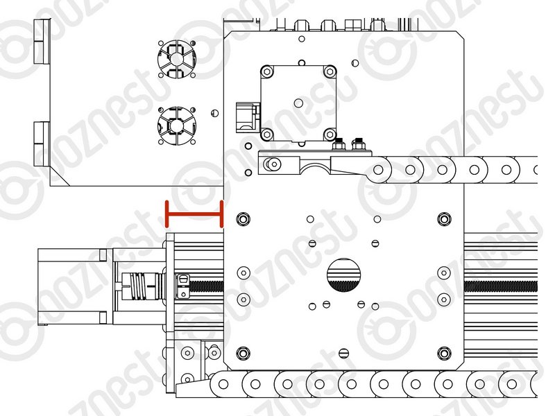
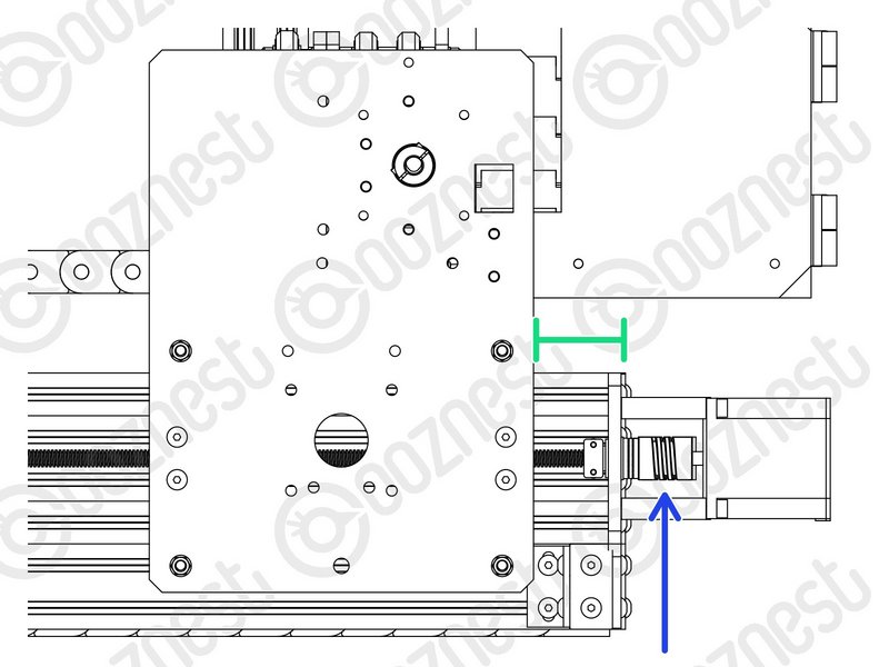
- On the left Y-Axis (The side with the Limit-Switch) measure the distance between the back of the Y-Carriage and Y-End-Plate.
- On right Y-Axis measure the same distance.
- Rotate the Flexible-Coupler by hand until it matches the left Y-Axis.
|
| Image |
Instructions |
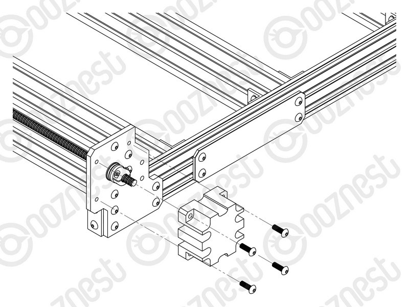 |
- Using 12 x M5-Button-Head-Bolt-16mm attach 3 x Lead-Screw-Caps over the bare ends of the X & Y-Axis Lead-Screws.
|
| Image |
Instructions |
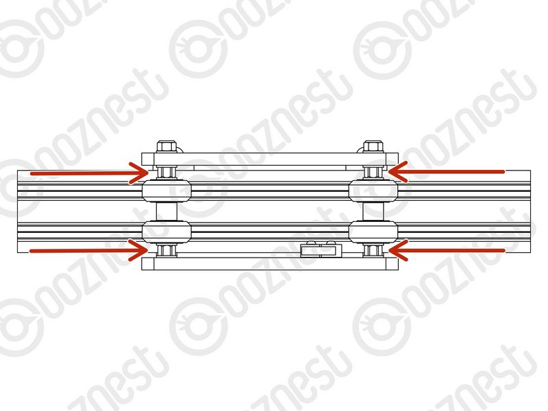 |
- In the 'Extras' box there is an Eccentric-Spacer-Spanner.
- This is shaped to give you access to all the Eccentric-Spacer-6mms without needing to move your machine.
- Eccentric-Spacer-6mms should be adjusted until there is a small amount of friction between the Solid-Wheel & Extrusion.
- Check there is also no play in the carriage if you try to wobble it. The Eccentric-Spacer-6mm will remove this if adjusted correctly.
- Adjust the Eccentric-Spacers on the X-Carriage.
- Adjust the Eccentric-Spacers on both Y-Carriages.
- Adjust the Eccentric-Spacers on the Z-Axis.
- We recommend periodically checking the Eccentric-Spacer-6mms throughout the use of the machine.
|
| Image |
Instructions |
 |
- It is nice to finally start moving the machine!
- Guide Complete - Proceed to 5.3 Spoilerboard
|