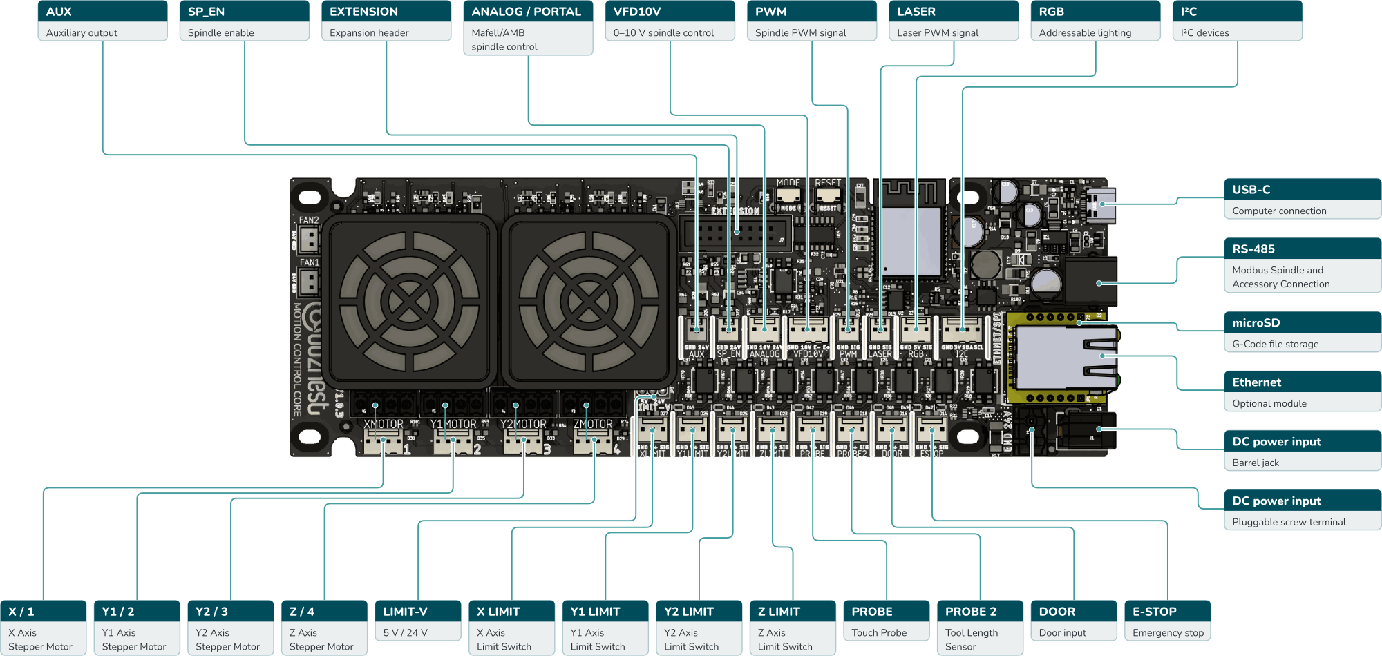
Follow a section below for each type of device. Before connecting, verify the Motion Control Core pin labels and the device’s connection instructions.
Unplug the power supply from mains, disconnect USB, and switch off and disconnect any separately powered equipment before working on the wiring.
Use a regulated 24V DC supply and choose a single connection method for the power supply.
Screw TerminalBarrel Jack
| Image |
Instructions |
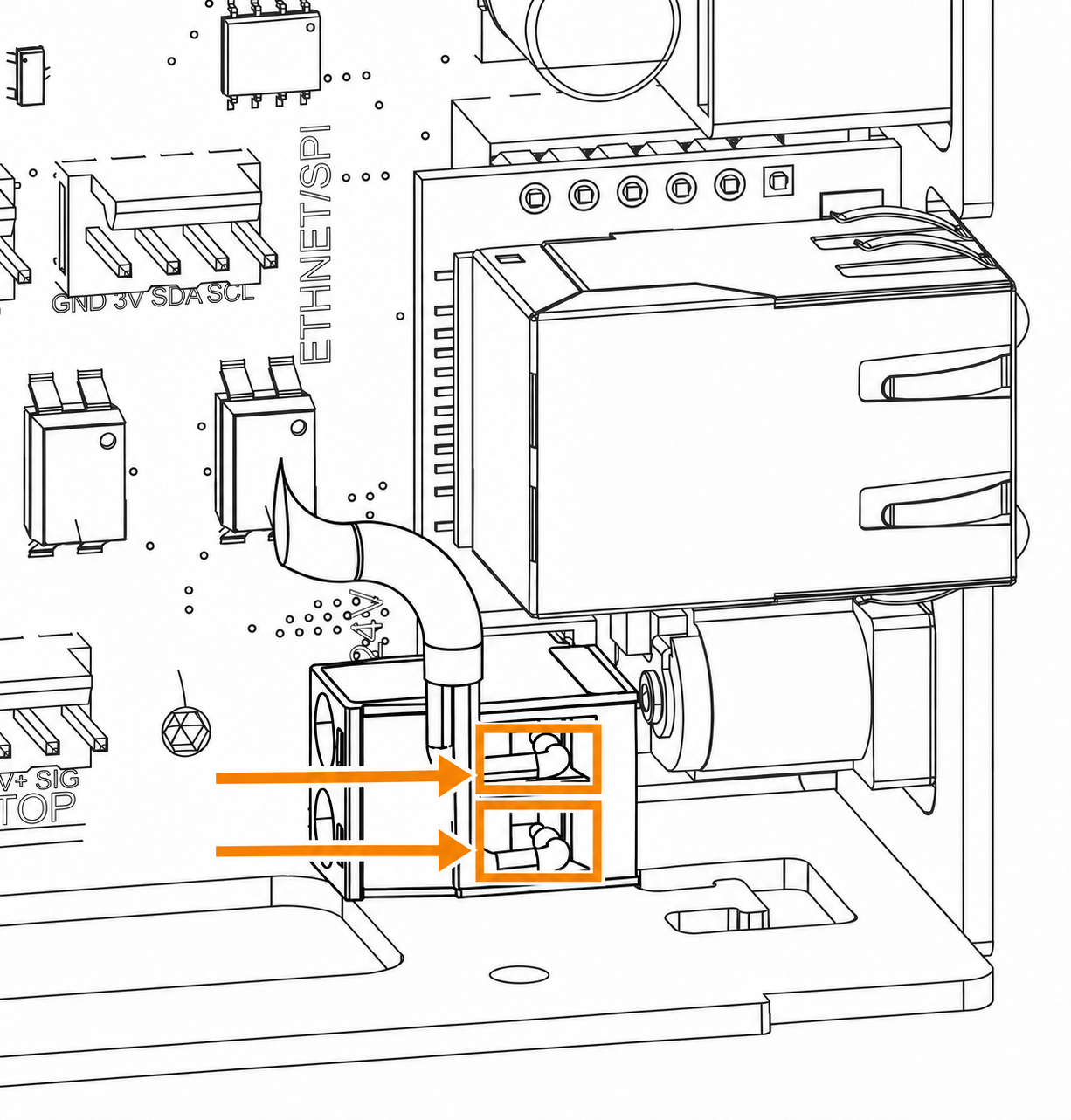 |
Connect power supply positive to controller 24V (Top) and negative to GND (Bottom) |
| Image |
Instructions |
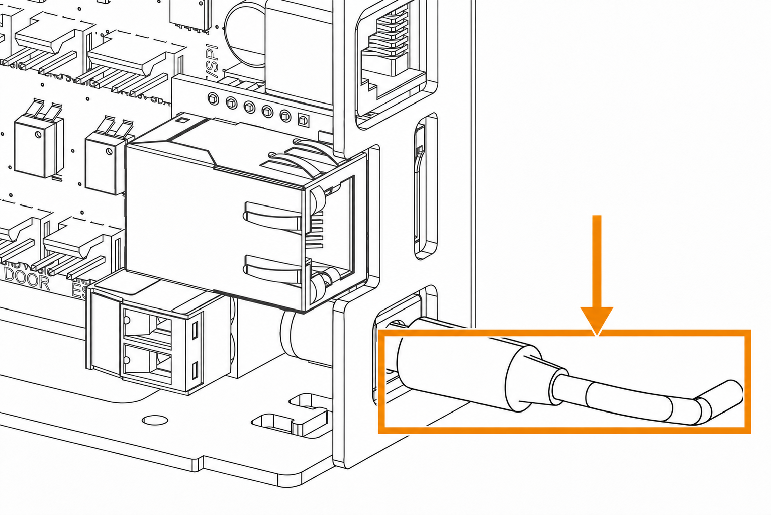 |
Use a centre-positive 5.5 × 2.1 mm plug |
For bare-wire motors, use the motor documentation to identify the two coil pairs. Connect one pair to A+ / A− and the other to B+ / B−. From left to right, the pin order is A+, A−, B−, B+.
Pin HeaderPluggable Screw Terminal
| Image |
Instructions |
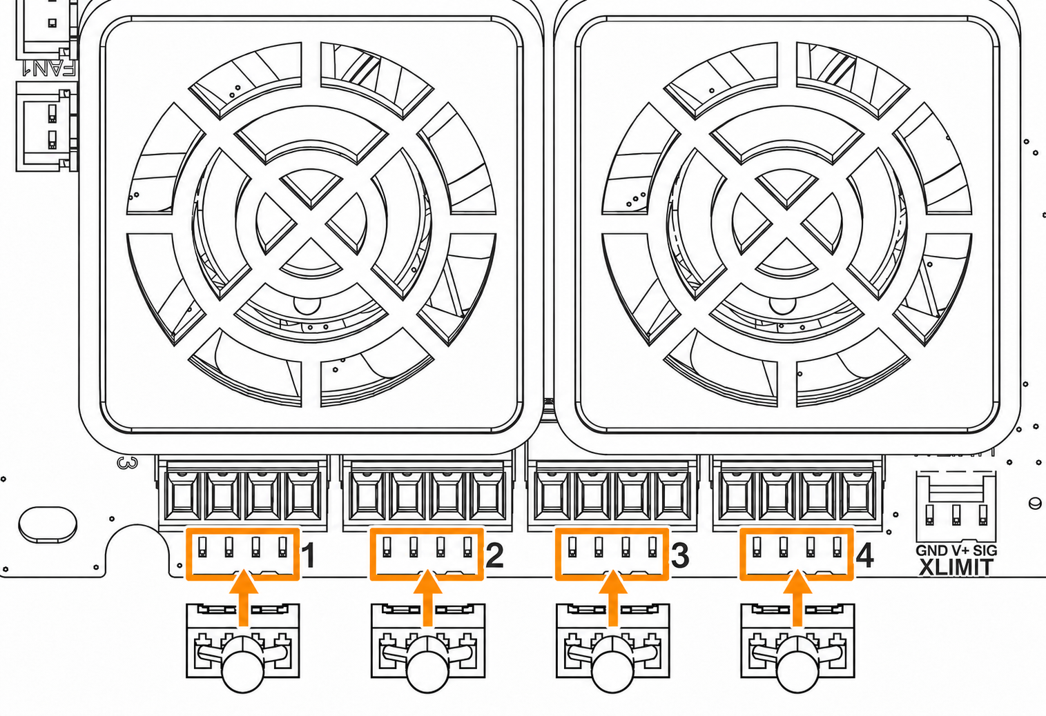 |
Plug the stepper motor into the corresponding axis output. From left to right, the order is: X-Axis (1), Y1-Axis (2), Y2-Axis (3), Z-Axis (4). |
| Image |
Instructions |
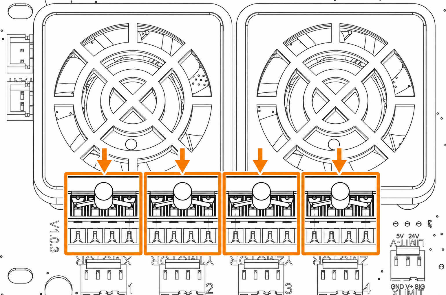 |
- Unplug the four-position screw terminal from the board.
- Loosen the screws and insert one motor wire into each opening. Use the pin order above: Coil A connects to pins 1 and 2, and Coil B connects to pins 3 and 4.
- Tighten each screw to secure the wires.
- Plug the screw terminal into the corresponding axis output. From left to right, the order is: X-Axis (1), Y1-Axis (2), Y2-Axis (3), Z-Axis (4).
|
| Image |
Instructions |
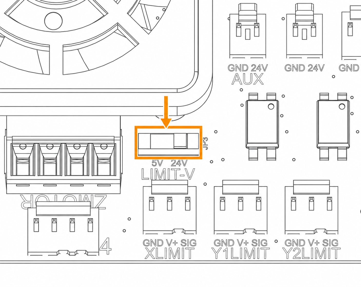 |
Set LIMIT-V to 24V for Inductive Limit Switches or 5V for Micro Lever Limit Switches. |
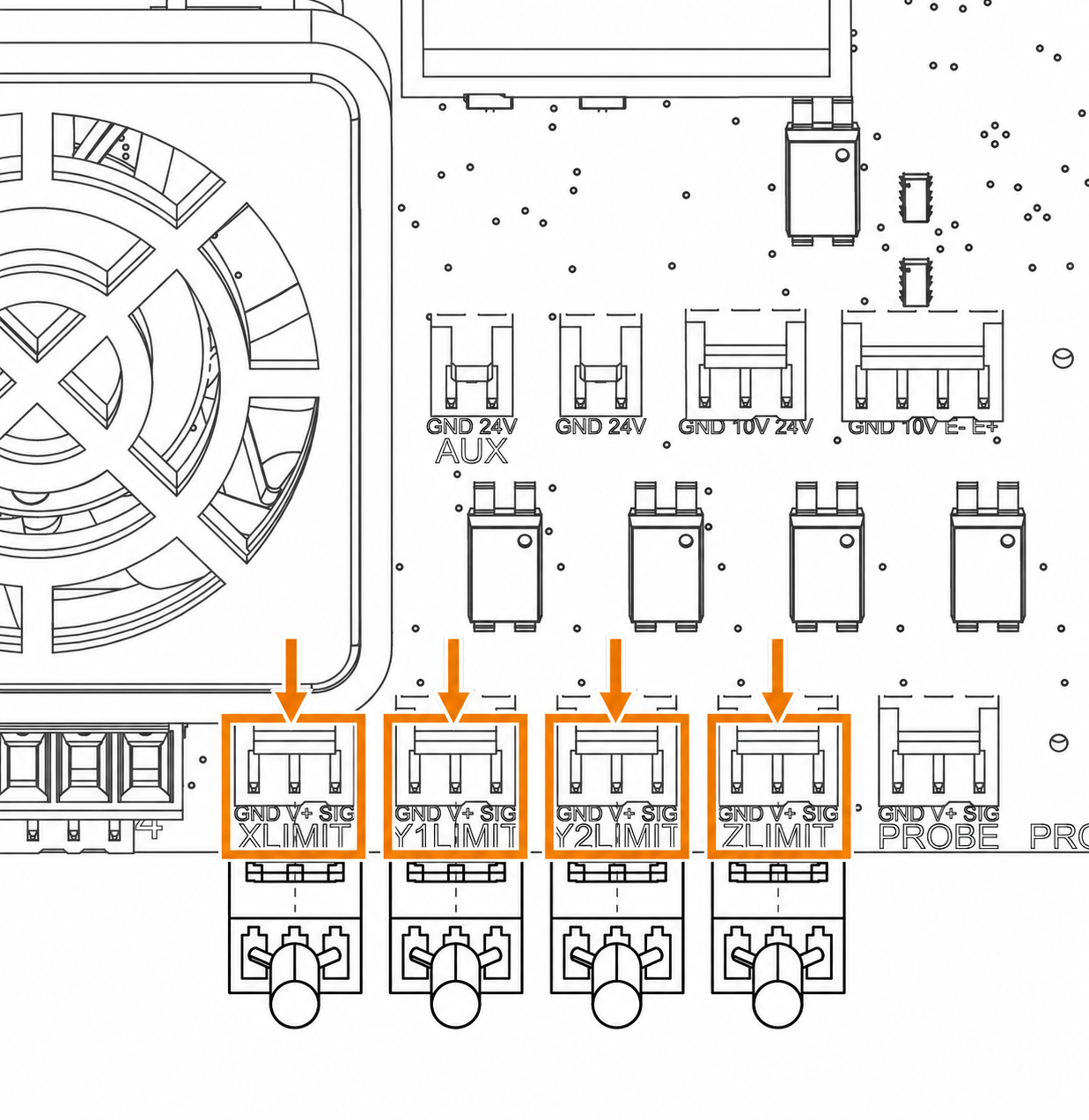 |
Plug the limit switch into the corresponding axis input. From left to right, the order is: X-Axis (1), Y1-Axis (2), Y2-Axis (3), Z-Axis (4). |
| Image |
Instructions |
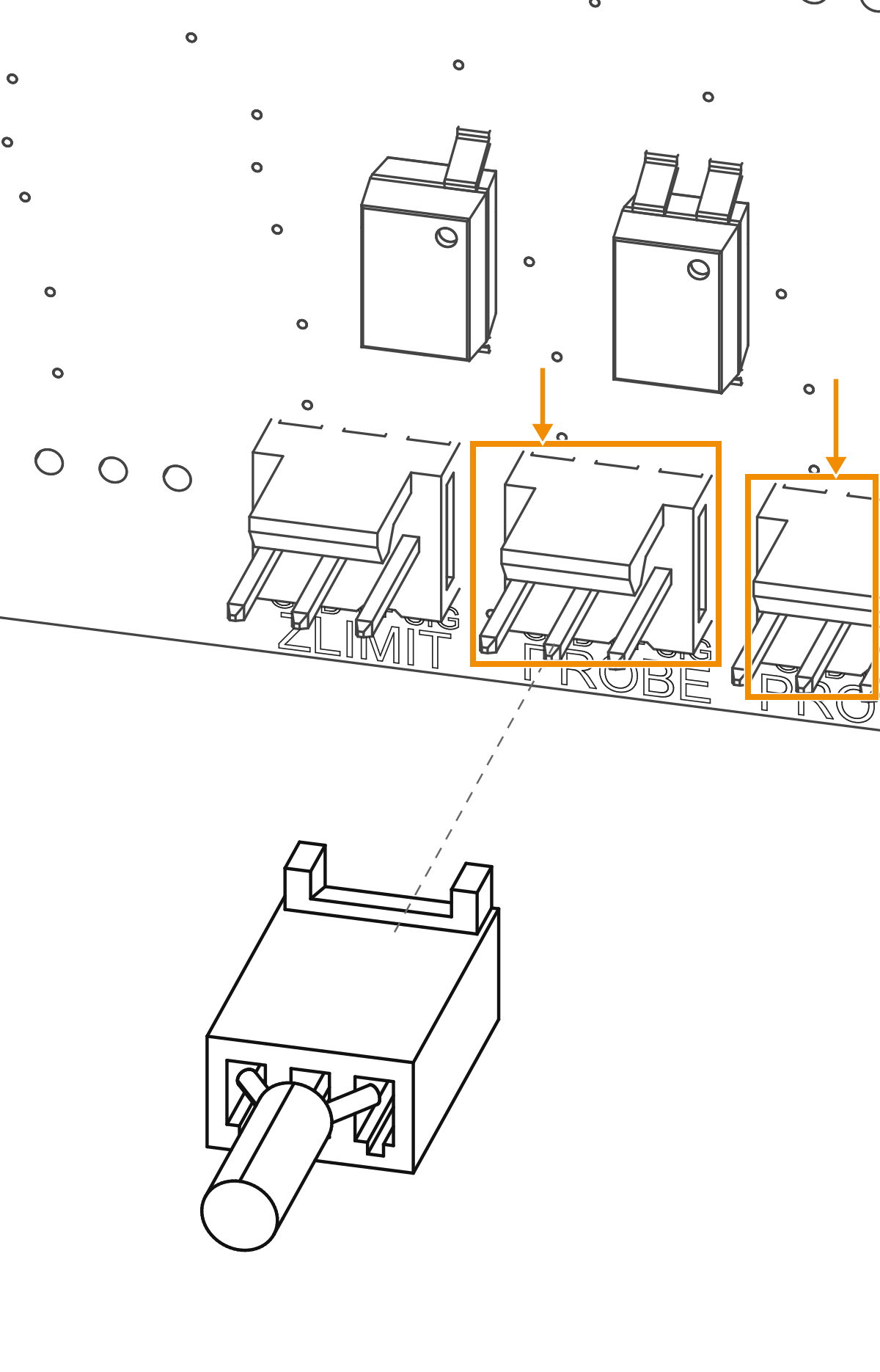 |
There are two identical probe inputs: PROBE and PROBE2. Use one for a plate probe and the other for a tool length setter. |
For a manually switched WorkBee Router Head, use its own power lead and switch. Set spindle control to Manual in Ooznest Control.
VFD10VRS-485 (Modbus VFD)PWMSP_EN (Spindle Enable)ANALOG (Portal)
| Image |
Instructions |
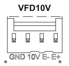 |
Connect 10V (0–10V speed signal) to the VFD’s speed input and GND to analog common. Connect E− and E+ to the VFD’s enable or forward input, following the VFD’s connection instructions. |
| Image |
Instructions |
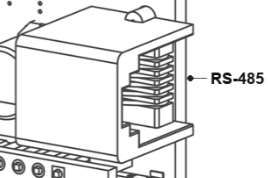 |
For a supported Modbus VFD, connect A to A, B to B, and GND if required. The socket pin order is 1–2: +5V, 3: B, 4: A, 5–6: GND. Check both ends of the cable before connecting. |
| Image |
Instructions |
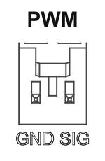 |
Connect SIG to the spindle controller’s PWM input and GND to its signal ground. |
| Image |
Instructions |
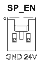 |
Connect 24V and GND to a relay module with a compatible 24V input. This switches the connected device on and off. |
| Image |
Instructions |
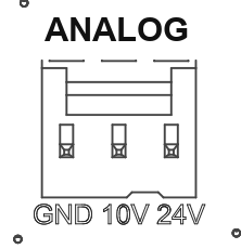 |
Connect GND to signal ground, 10V (0–10V speed signal) to the speed input, and 24V to the portal interface power input. See the Mafell wiring example below. |
The Mafell has a separate power lead. Disconnect power from both the Motion Control Core and the Mafell before wiring. Connect the three wires as shown below and insulate the unused black wire.
| Mafell pin |
Signal |
Cable colour |
Analog Pin |
| 1 |
UNC — portal interface supply |
Brown |
24V |
| 2 |
US — speed command |
White |
10V (0–10V signal) |
| 3 |
UO — overload runtime feedback |
Black |
Leave disconnected and insulate |
| 4 |
GND — signal reference |
Blue |
GND |
| Image |
Instructions |
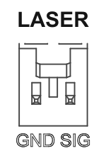 |
Connect SIG to the laser’s PWM input and GND to signal ground. Power the laser with its specified power supply and follow its connection instructions. |
| Image |
Instructions |
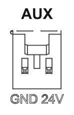 |
Use AUX to control a relay module with a compatible 24V input. The relay switches the external device, such as dust extraction, an air solenoid or a coolant pump. Control the output with coolant commands M8/M9. |
Use the onboard 5V supply only for LED loads under 500mA. For larger loads, connect a suitably rated external 5V DC adapter to the 5V and GND inputs on the LED strip or ring. Keep GND and SIG connected to the Motion Control Core, but leave its 5V pin disconnected.
| Image |
Instructions |
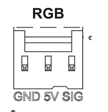 |
Connect addressable WS2812B LED strips or rings to the RGB port to reflect machine status. |
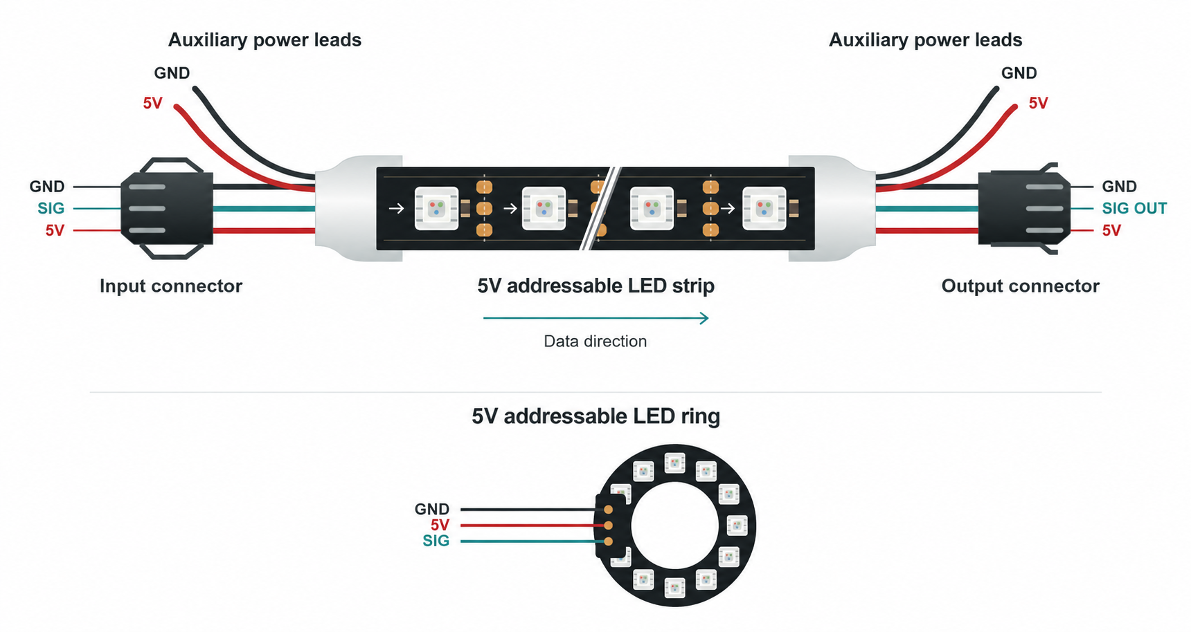 |
Connect the Motion Control Core’s GND and SIG to GND and SIG on the LEDs’ input connector. SIG may be marked DIN. For an LED strip, use the arrow printed on the strip to find the input end. The output connector passes data to the next strip. |
| Image |
Instructions |
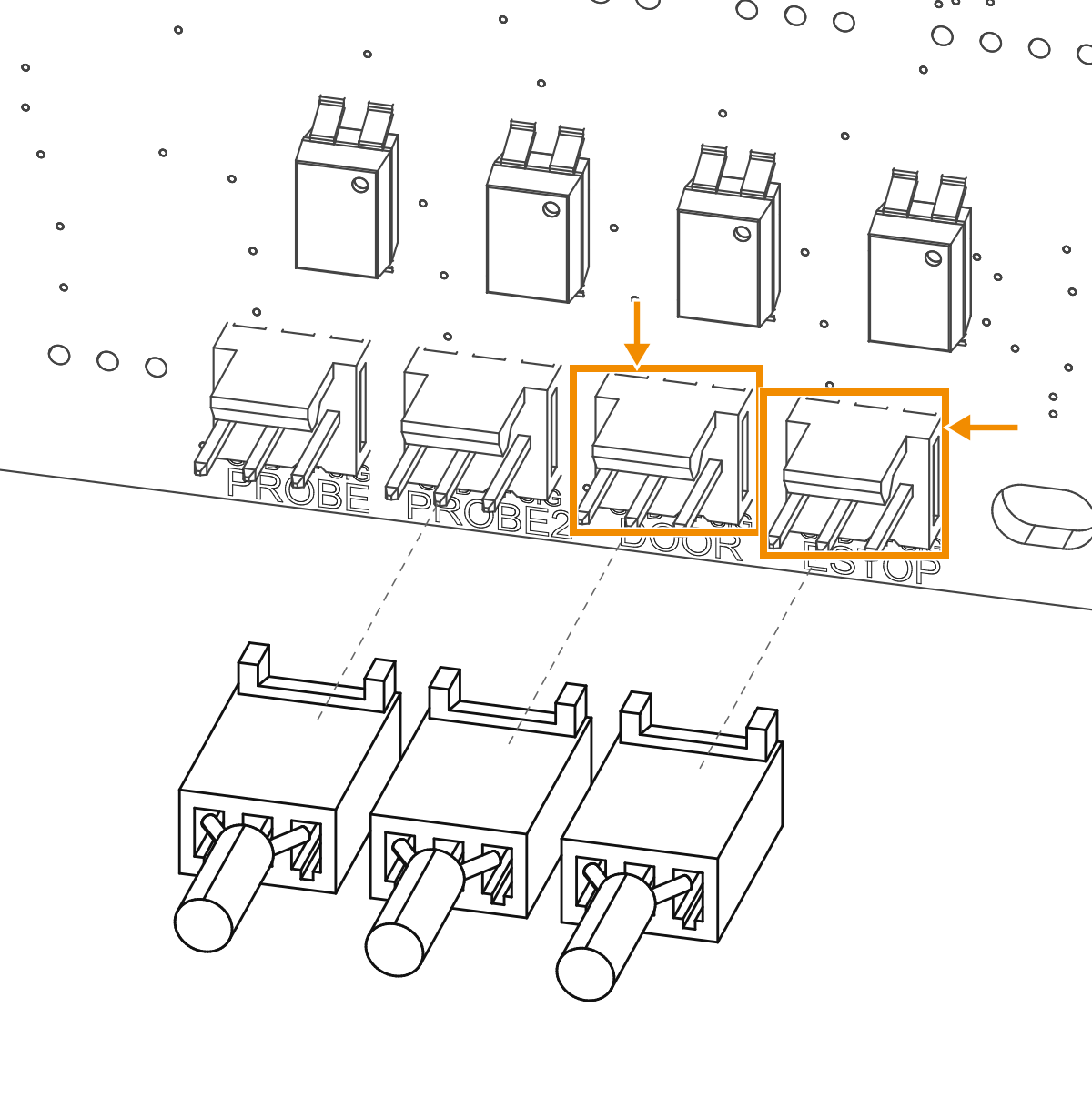 |
DOOR: Connect an enclosure door switch that triggers the machine to stop when the door opens.
ESTOP: If your emergency stop interrupts power to the controller, the controller detects the loss of power, so this additional input is not needed. |
These ports are intended for advanced use. Check the pin assignments and device requirements before connecting. Some devices may require firmware support.
Expansion PortI²C
| Image |
Instructions |
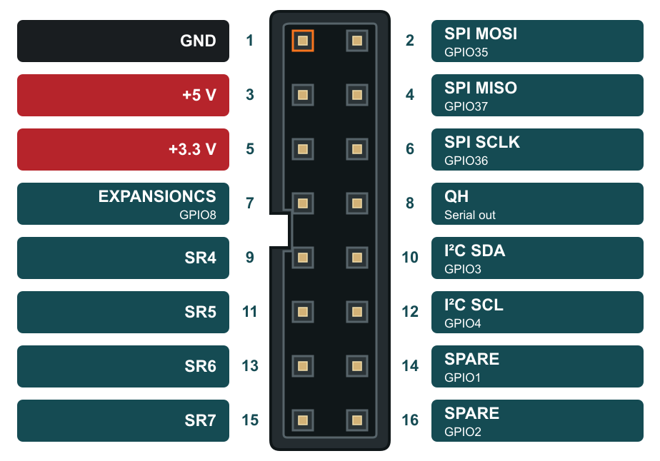 |
The extension port is a 16-pin IDC port. It is reserved for future expansions. |
| Pin |
Signal |
Pin |
Signal |
| 1 |
GND |
2 |
SPI MOSI (GPIO35) |
| 3 |
+5V |
4 |
SPI MISO (GPIO37) |
| 5 |
+3.3V |
6 |
SPI SCLK (GPIO36) |
| 7 |
EXPANSIONCS / shift-register latch (GPIO8) |
8 |
QH, shift-register serial output |
| 9 |
Spare shift-register Output 4 |
10 |
I²C SDA (GPIO3) |
| 11 |
Spare shift-register Output 5 |
12 |
I²C SCL (GPIO4) |
| 13 |
Spare shift-register Output 6 |
14 |
Spare MCU GPIO1 |
| 15 |
Spare shift-register Output 7 |
16 |
Spare MCU GPIO2 |
| Image |
Instructions |
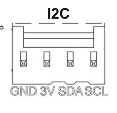 |
For 3.3V I²C devices, match GND, 3V, SDA and SCL. |
| Image |
Instructions |
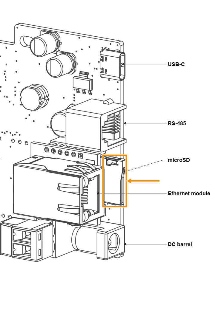 |
Insert a microSD card into the slot shown for onboard file storage. |
| Image |
Instructions |
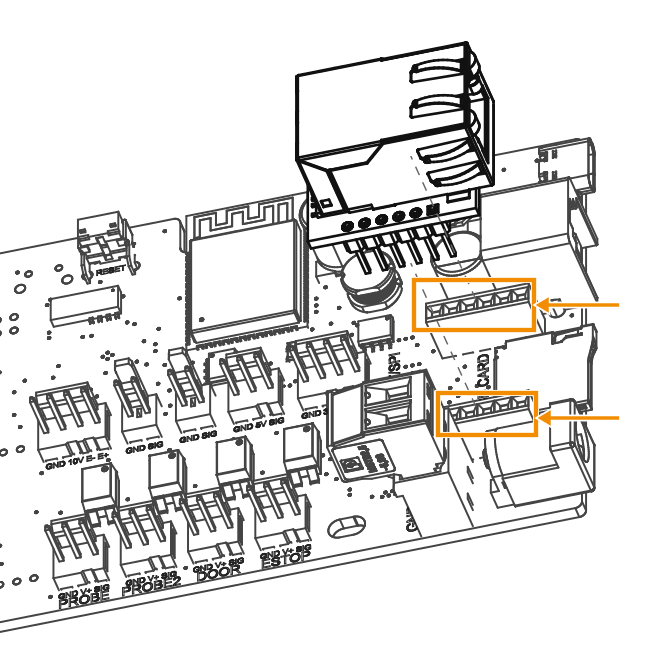 |
With power off, position the Ethernet module with its Ethernet jack facing outwards.- Align the pins with both socket rows on the Motion Control Core.
- Press the module down evenly.
- Check that all pins are correctly seated before switching power back on.
|
Before applying power, double-check:
- Power supply polarity.
- The LIMIT-V switch setting.
- All wiring and connections.
Keep the router, spindle or laser powered off when powering up the controller for the first connection.
Follow the First Connection and Setup guide to connect the controller to your computer and configure your machine.