You are going to need our Motor Wire and Limit Switch Cheat Sheet. We recommend printing it off!
| Image |
Instructions |
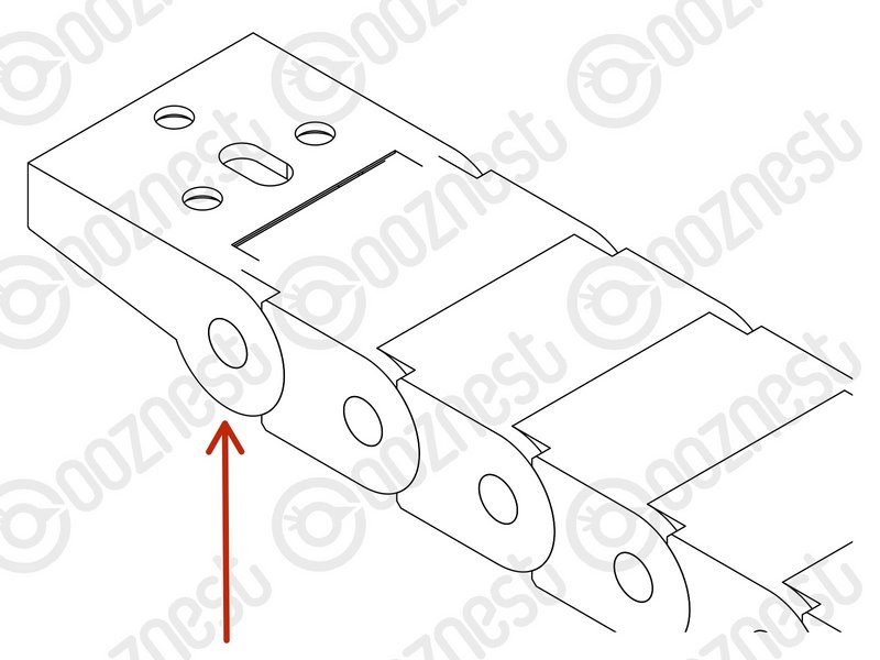 |
- Look at the X & Y Drag-Chains.
- On each end, there is an end mount.
|
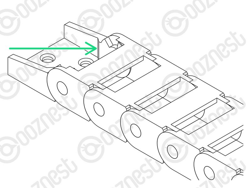 |
- If the end mount connects to the next link on the outside, this is known as the Moving End.
- If the end mount connects to the next link on the inside, this is known as the Fixed End.
- It is important you remember this, as these terms will be used going forward.
- Take a look at the links of the Drag-Chains. On one side of each link, there is a little slot.
- If you put a Flathead Screwdriver in this slot and twist. The top tab of the Drag-Chain will open.
- Knowing this can come in useful later!
|
The switch end of Limit-Switch-1 should be at the Fixed End of Drag-Chain-Y
The red/black crimped connectors should be at the Moving End of Drag-Chain-Y.
The black connector of the Motor-Wires should be at the Fixed End of Drag-Chain-Y.
| Image |
Instructions |
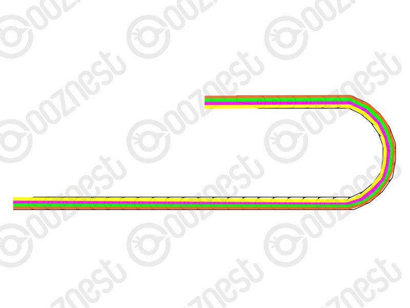 |
- Lay the Drag-Chain-Y flat out on a table.
- Feed through Limit-Switch-1.
- Feed through the output cable of the Emergency-Stop.
- Feed through Motor-Wire-4 and Motor-Wire-5.
- If you have the Ethernet version of the machine. Feed through the Ethernet Cable. (Orientation does not matter)
|
Position Drag-Chain-Y flat along the left side of the machine.The Fixed End of Drag-Chain-Y should be at the back of the machine.
| Image |
Instructions |
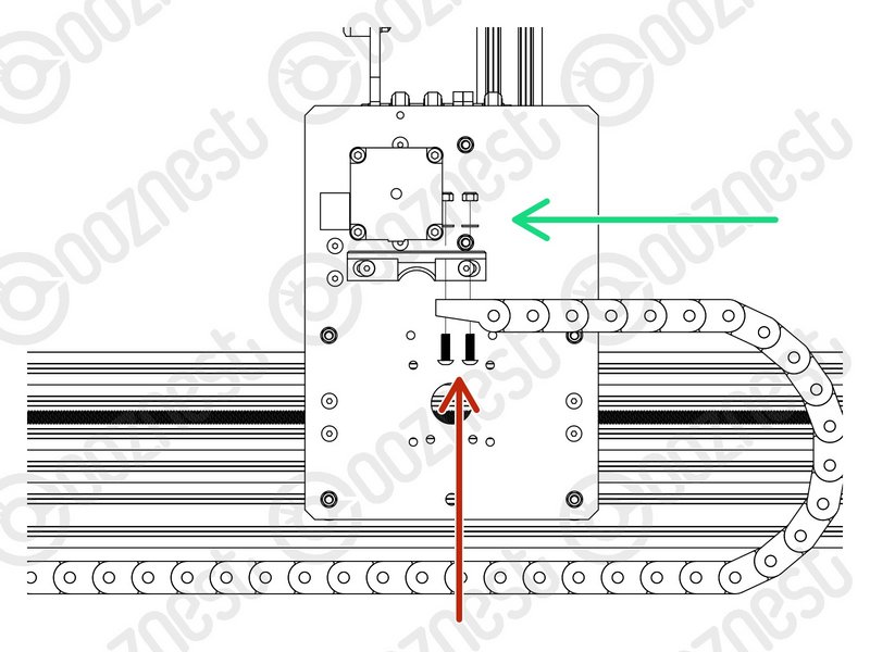 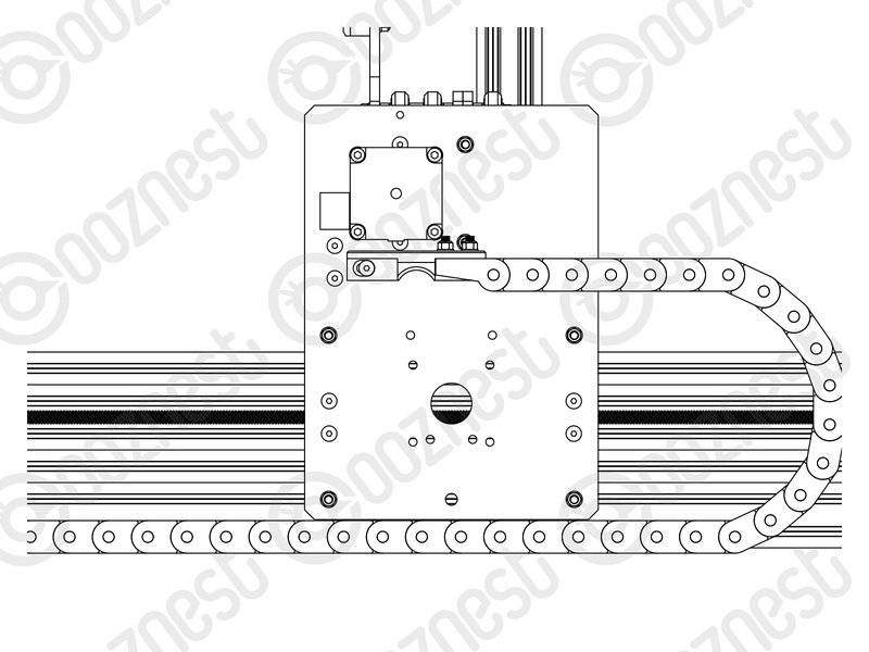 |
- Bring the Moving End of Drag-Chain-Y upwards to the Drag-Chain-Mount on the Y-Carriage-Left.
- Attach it to the 3 holes on the Drag-Chain-Mount using 3 x M5-Button-Head-Bolt-16mm through the bottom.
- Then add 3 x Precision-Shims and 3 x M5-Nyloc-Nuts on the opposite side of the Drag-Chain-Mount.
|
The Fixed End of Drag-Chain-Y will be fixed into position in a later guide.
The black connector of Motor-Wire-6 should be at the Moving End of Drag-Chain-X.
| Image |
Instructions |
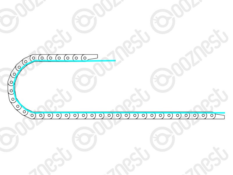 |
- Lay the Drag-Chain-X flat out on a table.
- Feed through Motor-Wire-6
|
| Image |
Instructions |
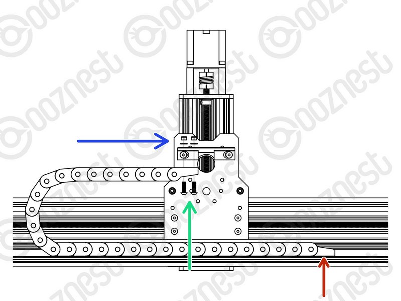 |
- Position Drag-Chain-X flat along the back of the X-Gantry sitting on top of Extrusion-B.
- If looking from the back, the Fixed End of Drag-Chain-X should be at the right side of the machine.
|
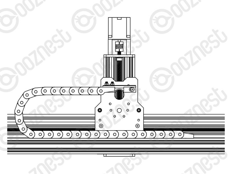 |
- Bring the Moving End of Drag-Chain-X upwards to the Drag-Chain-Mount on the X-Carriage.
- Attach it to the 3 holes on the Drag-Chain-Mount using 3 x M5-Button-Head-Bolt-16mm through the bottom.
- Then add 3 x Precision-Shims and 3 x M5-Nyloc-Nuts on the opposite side of the Drag-Chain-Mount.
|
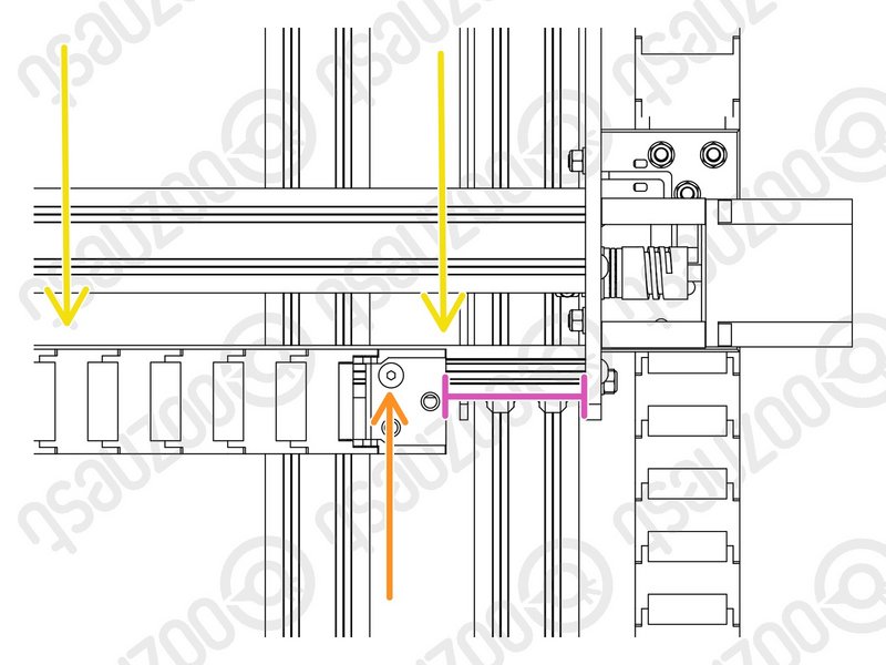 |
- Attach the Fixed-End of Drag-Chain-X to Extrusion-B using 1 x M5-Button-Head-Bolt-8mm and a M5-Drop-In-Tee-Nut.
- There should be a 90mm gap between the end of Drag-Chain-X and the inside of the Y-Carriage. You can reduce this distance once you start using the machine to stop Drag-Chain-X from hitting the Y-Carriage at the opposite end.
- Drag-Chain-X should run flush with Extrusion-B.
|
| Image |
Instructions |
 |
- Don't worry we will tidy up all the messy wires!
- Guide Complete - Proceed to 3.2 Limit Switches
|