You are going to need our Motor Wire and Limit Switch Cheat Sheet. We recommend printing it off!
Any unneeded slack in wires below should be pulled out at the Fixed End of the Drag-Chain-X.
If you have the Touch Probe you can route that wire through Drag-Chain-X like Step 4 of Assembling Your Original WorkBee XYZ Touch Probe
| Image |
Instructions |
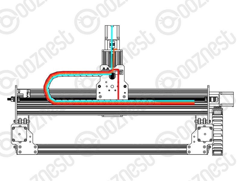  |
- Motor-Wire-6 is coming out of the Moving End of Drag-Chain-X.
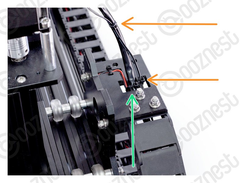
- Feed Motor-Wire-6 through the Drag-Chain-Mount and plug it into the pigtail on the Z-Axis Stepper-Motor.
- Feed the wire from Limit-Switch-2 through the Drag-Chain-Mount and then through Drag-Chain-X so it comes out the Fixed End.
- Secure the Limit-Switch-2 wire and Motor-Wire-6 together to the Drag-Chain-Mount using a small cable tie as in Image 2.
- Make sure there is enough slack on Motor-Wire-6 for the full travel of the Z-Axis.
- Secure the wire to the Drag-Chain-Mount using a small cable tie. Then secure it along Motor-Wire-6.
|
Any unneeded slack in wires below should be pulled out at the Fixed End of the Drag-Chain-Y.
| Image |
Instructions |
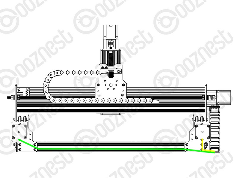 |
- Motor-Wire-5 is coming out of the Fixed End of Drag-Chain-Y.
- Tuck this wire into the bottom slot of Extrusion-A
- Plug it into the right Y-Axis Stepper-Motor (If looking from the front)
- Motor-Wire-4 is coming out of the Fixed End of Drag-Chain-Y.
- Plug it into the left Y-Axis Stepper-Motor (If looking from the front)
|
| Image |
Instructions |
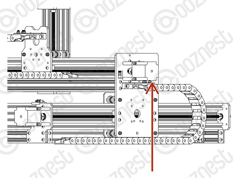 |
- Plug Motor-Wire-3 into the X-Axis Stepper-Motor.
- Leave it hanging for now.
|
| Image |
Instructions |
 |
- That is all the wires routed. Now time to plug it all in!
- Guide Complete - Proceed to 3.5 Controller
|