Use Tools > Bowl Cutter to generate a bowl or tray program centred on the active work X/Y origin.
Secure stock large enough for the entire bowl and surrounding workholding. Check stock thickness against the final depth and leave the required bottom thickness. Keep clamps and screws outside every cutting and travel move. Fit a suitable cutter with the spindle isolated.
¶ Step 1: Establish the origin and shape
| Instructions |
Preview |
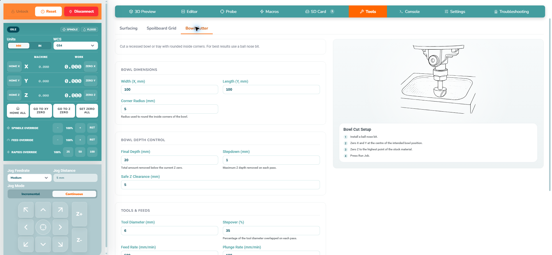
- Fit the intended cutter; a ball-nose cutter can improve the finish of curved surfaces.
- Set X/Y zero at the centre of the intended bowl and Z zero at the highest point of the stock.
- Width / Length: bowl dimensions.
- Corner Radius: controls rounded plan-view corners and the generated narrowing towards the bottom. It is not the cutter radius; enter the physical cutter diameter separately.
|
 |
| Instructions |
Preview |
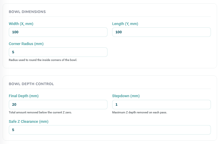
- Final Depth: total depth below Z zero. Stepdown: maximum depth increment per pass.
- Safe Z Clearance: travel height above work Z zero. Check clamps and available Z travel.
- Tool Diameter: actual cutter diameter. Stepover: pass spacing as a percentage of diameter; smaller spacing adds passes and can reduce surface scallops.
- Feed / Plunge: cutting and downward feed rates. RPM: spindle speed command when supported. Set dial manually on manual spindles.
|
 |
¶ Step 3: Generate and inspect
| Instructions |
Preview |
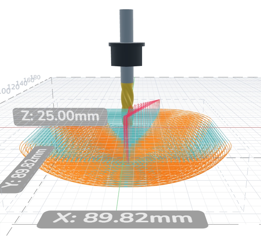
- Click Generate G-Code. The new program is loaded into 3D Preview.
|
 |
- Check the centre, boundary, corner shape, first plunge, final depth and every travel move against the real setup.
- Check remaining bottom thickness and that neither the tool nor holder reaches workholding.
- Inspect the spindle start and stop commands in the generated file before running.
|
 |
For a manual router, set the speed and start it yourself. For a controlled spindle, verify that its generated start command is appropriate and that it reaches speed before cutting. Start extraction, then click Run Job > Run (Streaming) and read the confirmation. Keep the computer connected and watch the first moves.
See First Job for the shared pre-flight and job-control procedure, or G-code Editor to save and inspect the generated file.
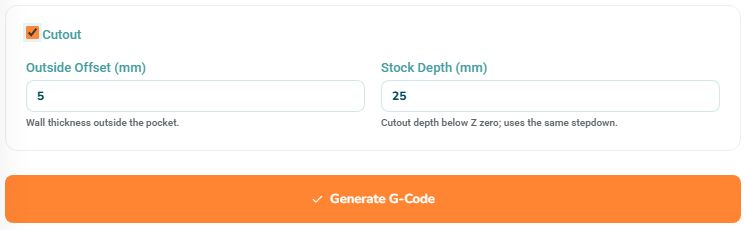
Enable Cutout before generating to cut the bowl free from its parent stock after pocketing. Leave it unticked to generate only the pocket; the offset and stock-depth inputs remain disabled.
| Instructions |
Preview |
- Tick Cutout.
- Outside Offset: wall thickness outside the pocket. Tool radius compensation is included automatically; do not add the tool radius to this value.
- Stock Depth: final cutout depth below the same stock-top Z zero. It must exceed Final Depth to leave a bottom in the bowl.
- The cutout uses the same cutter, Stepdown, feed and plunge rates.
|
 |
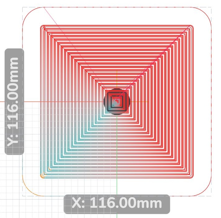
- Click Generate G-Code again and inspect the outside contour in 3D Preview.
- Check clearance around the full outside cut, including the cutter and holder.
- Example shown: a 100 × 100 mm pocket, 5 mm outside offset and 6 mm cutter produce a 110 × 110 mm outside bowl shape and a 116 × 116 mm tool-centre path.
|
 |
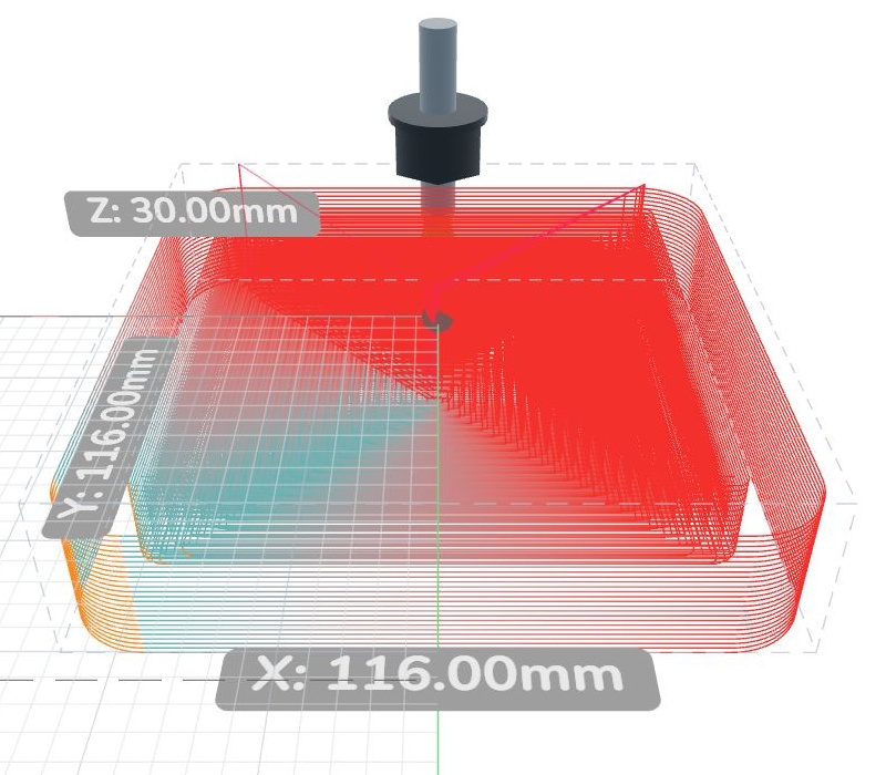
- Check that the cutout reaches the intended stock depth after the pocket is finished.
- Example shown: 20 mm pocket depth and 25 mm stock depth leave a 5 mm bottom; the cutout steps down to 25 mm below Z zero.
- Secure the bowl so it cannot move as the final pass releases it. No holding tabs are generated.
|
 |