Use this guide to check your setup and run a simple, shallow first job. Ooznest Control runs a prepared G-code file; it does not decide whether the cutter, cutting settings or workholding are suitable.
Complete First connection and setup before continuing. The screenshots show example files and coordinates, not settings to copy to your machine.
| Instructions |
Preview |
- To complete this guide you will need a 250x250x18mm piece of MDF.
|
 |
- Use four wood screws to secure the MDF to the spoilboard.
- Keep the screws outside the complete cutting path and make sure the MDF is square with the machine.
- Make sure the screw heads are flush with the MDF surface.
|
 |
Isolate the router from mains power before handling the cutter or collet. Choose your router below and follow its manufacturer's fitting instructions.
WorkBee Router HeadMafell
| Instructions |
Preview |
- Always use the correct collet size for the cutter.
|
 |
- Fit the collet and nut, then insert the end mill to the depth specified by the cutter and router manufacturers.
- Use the side button only for hand tightening. Fully tighten using a 13 mm spanner on the shaft flats and the supplied 22 mm spanner on the nut.
|
 |
| Instructions |
Preview |
- Always use the correct collet size for the cutter.
|
 |
- Click the collet into the nut first, then insert the end mill to the depth specified by the cutter and router manufacturers.
- Tighten and maintain the collet according to the instructions for your Mafell model, including its specified torque and lubricant.
|
 |
| Instructions |
Preview |
- Turn off and unplug the router from mains power.
- Find the 1/4-inch square-cut end mill in the Extras Box.
- Secure it in a matching 1/4-inch collet, following the appropriate router instructions in Step 2.
|
 |
- While tightening, set the end mill stick-out to 30 mm using the Height-Reference-Tool, while retaining the manufacturer's required shank engagement. Do not use that stick-out if it compromises secure clamping.
|
 |
¶ Step 4: Connect and home
| Instructions |
Preview |
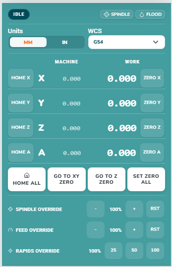
- Turn on the machine, open Ooznest Control and connect using your configured USB or network connection.
- With the travel area clear, click Home All.
- Wait for homing to finish and the controller to return to IDLE.
- Homing establishes the machine reference, not the workpiece origin.
|
 |
Use Step 5 without a probe, or Step 6 with a touch probe. These are alternatives: complete one method, then continue to Step 7. Keep the spindle stopped throughout zeroing.
| Instructions |
Preview |
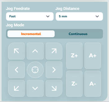
- Use the jog buttons to centre the end mill over the front-left corner of the MDF.
- Use Slow feedrate, Incremental mode and small distances near the material or clamps.
- Check direction and clearance before each move. Do not set all axes to zero while the tip is still at an arbitrary height above the material.
|
 |
- With X/Y aligned at the corner, carefully lower the stationary tip until it is level with the MDF's top surface. Do not drive it into the material.
- Only when all three axes are at the intended job origin, click Set Zero All.
- This changes work coordinates without moving the machine. The older photo shows the physical position; use the current Ooznest Control button label.
|
 |
- Raise Z to clear the material and all workholding while remaining within available travel.
- Continue to Step 7; do not repeat zeroing with the probe.
|
 |
Use this method instead of Step 5 if you have a touch probe.
| Instructions |
Preview |
- Seat the touch probe over the front-left corner of the MDF, with its locating faces against the material.
- Make sure the probe sits securely and cannot rock or move.
- Use Slow jog feedrate, Incremental mode and small movements to centre the endmill in the probe’s Start Here hole.
- Position the endmill tip approximately level with the top of the probe, without touching it.
- Attach the crocodile clip to a clean, conductive part of the endmill.
|
 |
- Connect the probe lead to the machine’s probe connector.
- Keep the cable clear of moving parts, with enough slack for the probing movement.
|
 |
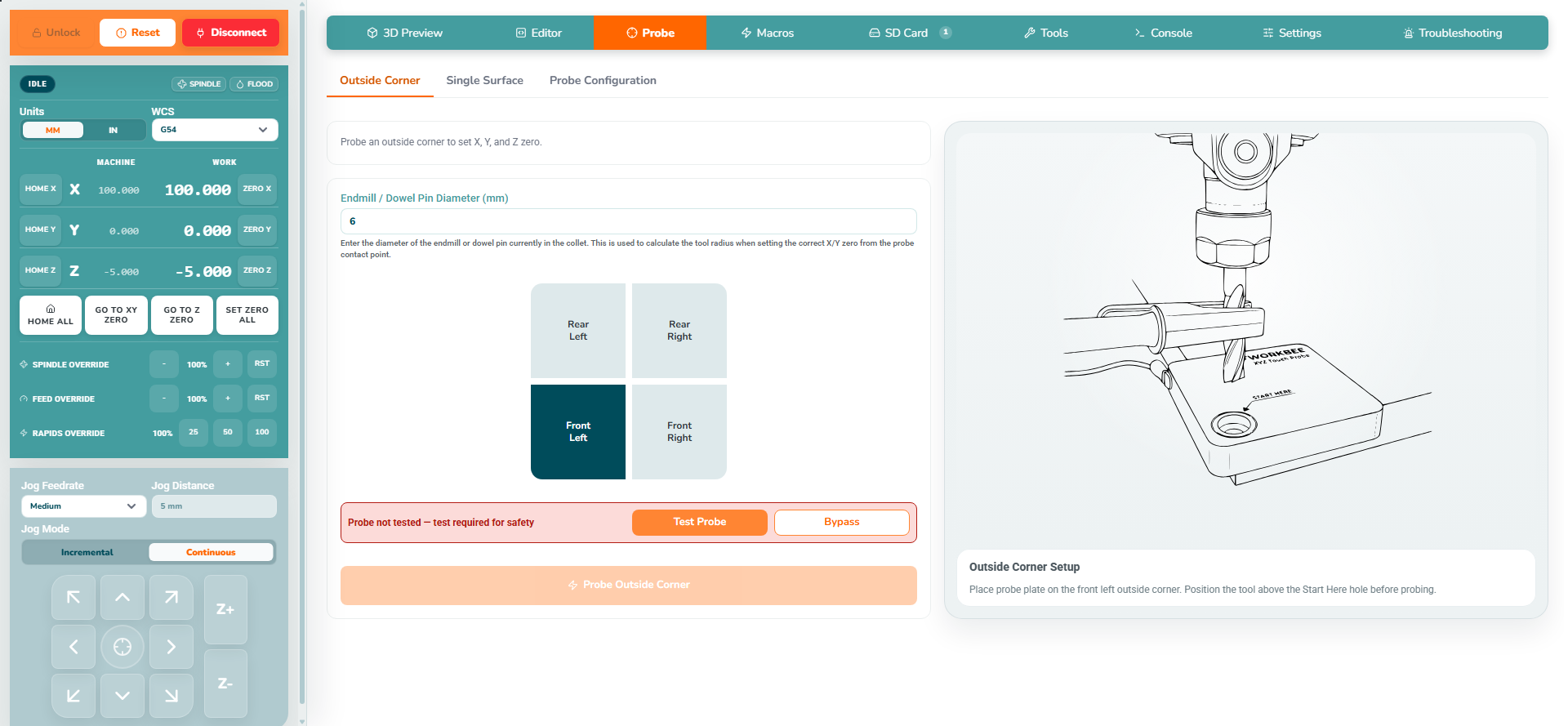
- Open Probe → Outside Corner.
- Confirm that the probe configuration matches your fitted touch probe.
- Select the Front Left corner to match the probe’s physical position.
- Enter the actual diameter of the endmill or dowel pin in the collet. Use 6.35 mm only if that is the diameter of your tool.
|
 |
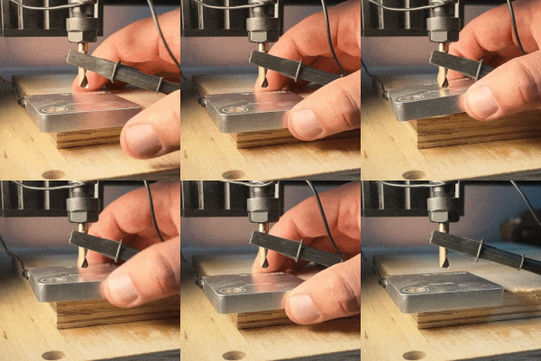
- Run Test Probe and follow its instructions.
- With the crocodile clip attached and the machine stationary, lift the probe plate to touch the endmill, as shown.
- Confirm contact is detected, then move the plate away and confirm release is detected. Do not bypass a failed test.
- Reseat the probe securely on the front-left corner and return the endmill to the starting position shown above.
|
 |
- Start the Outside Corner probing routine.
- Wait for successful completion and for all movement to stop.
- Probing establishes work zero automatically. Do not press Zero or Set Zero All afterwards.
|
|
- Once the machine has stopped, remove the crocodile clip, unplug the probe and remove it from the material.
- Ensure the probe, clip and cable are completely clear before continuing.
|
 |
- Raise the cutter clear of the material and clamps before checking the corner position.
- With the movement path clear, use Go to XY Zero to check alignment above the front-left corner.
- Use Go to Z Zero to check that bit is at the correct Z height.
|
 |
¶ Step 7: Load and review the program
| Instructions |
Preview |
|
 |
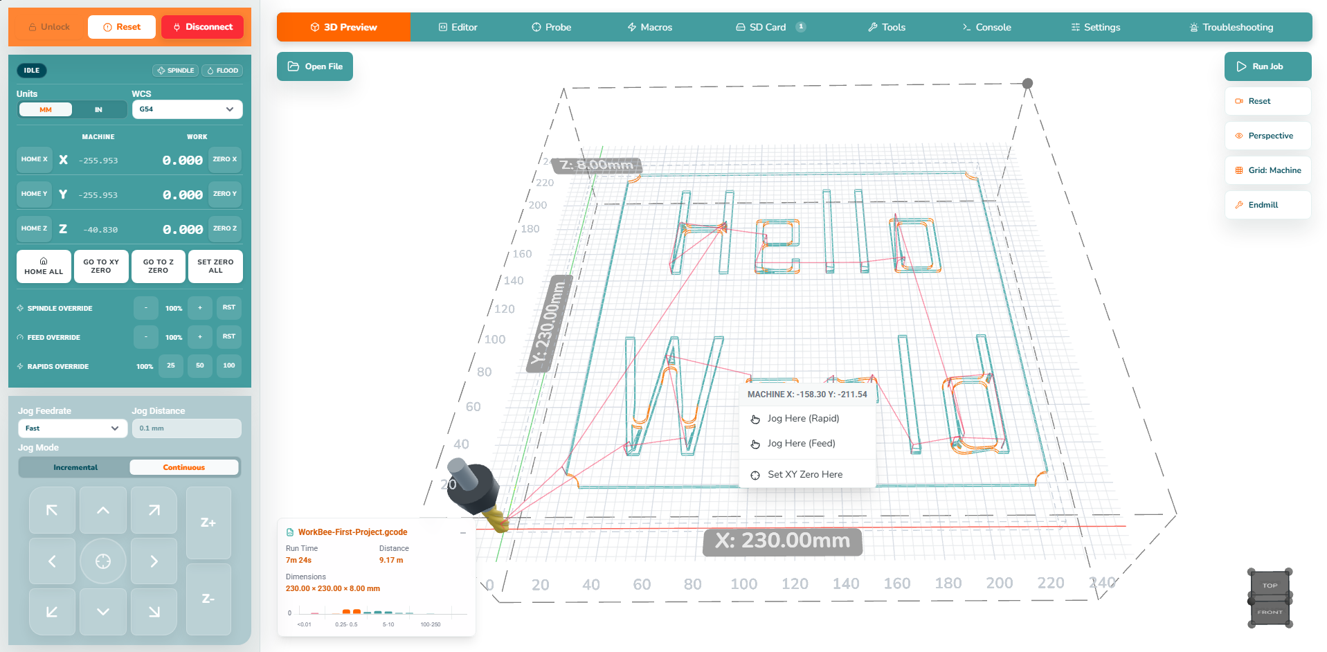
- In 3D Preview, click Open File and select the intended G-code file from your computer.
- Check that the loaded filename is the one you intend to run.
- Orbit, pan and zoom to inspect the full toolpath. Compare the job origin, cutting depth and travel area with your physical setup.
- Check the program's units, work coordinate system and clearance moves. Check that rapid moves and the toolholder clear the material and clamps.
- The displayed cutter is a preview model. Changing it does not change the physical cutter or the cutting settings in the file.
- If the preview or setup is wrong, correct the program or setup before running.
|
 |
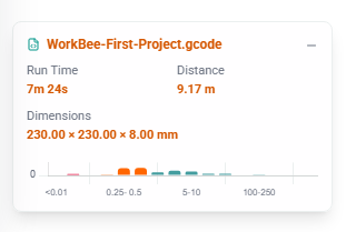
- Use Job Statistics to check the filename and X, Y and Z dimensions against your intended job.
- Run Time is an estimate; actual time can change with acceleration, overrides and controller behaviour.
- Distance is parsed toolpath travel.
- Segment graph: groups moves by length and can identify short-segment jobs that may need optimisation.
|
 |
| Instructions |
Preview |
- Mafell: Set the thumbwheel on the Router Head to Number 6 (25000 RPM).
- WorkBee Router Head/Katsu: Set the thumbwheel on the Router Head to Number 4 (25000 RPM).
|
 |
| Instructions |
Preview |
- Adjust the height of the Dust Shoe so the tip of the brushes are just touching the MDF piece we are cutting.
- Fix into position using the clamping bolt on the side of the Dust Shoe.
|
 |
The router instructions here are for the manually switched routers shown above. If your machine has controller-operated spindle control, verify its configuration and program commands instead; do not assume the manual switch procedure applies.
| Instructions |
Preview |
- The MDF is secure.
- Work zero is set.
- The work area is clear.
- The endmill is secure.
- Read the safety instructions for your machine: WorkBee Z2 or WorkBee Z1+.
- Switch on the router head.
- Switch on the extractor, if fitted.
|
 |
| Instructions |
Preview |
- Make a final check of the cutter, material, clamps, work zero, clearance, spindle operation and extraction.
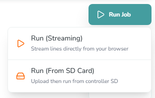
- Click Run Job, then choose Run (Streaming) to send the reviewed program from the computer to the controller.
- Read the confirmation before approving it: approval starts the job.
- Keep the computer connected and available while streaming.
- Watch the real machine, especially the first rapid move, plunge and cut. Screen animation is not a substitute for observing the tool and workholding.
|
 |
| Instructions |
Preview |
- Pause requests a controlled hold. Wait for motion to stop. It does not isolate power or guarantee that the spindle has stopped.
- The button becomes Resume. Resume only after checking why the job was paused and confirming it is safe to continue.
- Stop asks for confirmation, then resets the controller and ends the job. Treat it as an interrupted job, not a resumable pause.
- After stopping, inspect the machine and re-establish a safe setup before considering a restart. Do not assume restarting the file from the beginning is safe.
- For an immediate hazard, use the machine's physical emergency stop. Pause, Stop and Disconnect are not substitutes for it.
|
 |
- For streaming, the progress bar and percentage show how much of the program has been sent, not how much physical motion has finished.
- Line shows the current sent-line count and total streamed lines.
- Elapsed shows time since the job started, including time spent paused.
- The smaller buffer bar shows sent data awaiting controller acknowledgement. Motion may still remain when the progress reaches 100% as the controller buffers a few moves ahead.
- Wait for the controller to return to IDLE and check the real machine has stopped before approaching it.
|
 |
¶ Step 13: Finish and inspect
| Instructions |
Preview |
- Wait for IDLE and for all machine motion to finish.
- Switch off a manually controlled router. Wait for the cutter to stop completely, then isolate power before handling the cutter or workpiece.
- Remove the screws and lift the project clear.
- Inspect the completed shape and depth. Investigate loose workholding, missed areas or an unexpected cut before running another job.
|
 |
| Instructions |
Preview |
|
 |
Review the Main Screen guide for more detail on coordinates, jogging, preview controls and job statistics.