Use Probing to establish work coordinates from a physical contact measurement. Outside Corner establishes a stock corner; Single Surface establishes one selected axis. Choose the routine for your task rather than running both in sequence.
Stop the spindle before fitting the probe or starting a routine. Confirm the configured probe dimensions and the actual cutter or pin diameter. Keep the cable clear of moving parts.
Your probe may already be configured - if you set it up while running the Configuration Wizard during the First Connection and Setup step. If so, you can skip this step. If you have a 3rd party probe, or want to make changes to the behaviour of the probing routines, you can use Probe Configuration to change settings.
| Instructions |
Preview |
- Open Probe → Probe Configuration. Use the dimensions of your actual plate.
- Plate Offset X / Y: distance from each plate contact face to the corresponding workpiece face. Plate Thickness Z: distance from its top contact face to the workpiece surface.
- Corner Start-Hole Inset: X/Y travel from the Start Here hole towards the plate centre.
- Probe Feedrate: contact-search speed.
- Click Apply after checking every value.
|
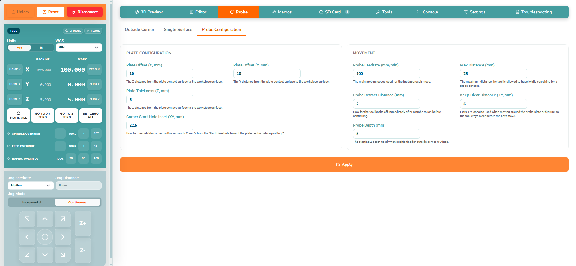 |
Automatic Outside Corner uses fixed 25 mm search moves on Z, X and Y. Its retract, clearance and side-depth positions are also fixed. The Max Distance, Probe Retract Distance, Keep-Clearance XY and Probe Depth fields do not change those moves.
| Instructions |
Preview |
- Connect the plate and clip as required by the probe instructions.
|
 |
- Click Test Probe, follow its prompts and confirm both released and contacted states are detected.
- If it fails, stop and investigate the cable, clip, contact surfaces and Signals display. Do not start a routine.
- Bypass deliberately skips the safety test. Do not use it to work around a failed contact test; it is not proof that the probe is functional.
|
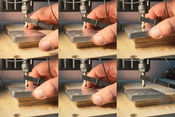  |
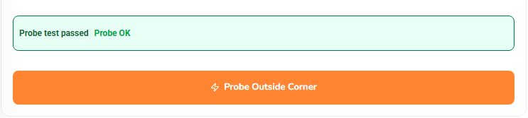
- A successful contact-and-release test enables the Probe buttons.
- Return the tool and plate to the routine's starting position before continuing.
|
 |
| Instructions |
Preview |
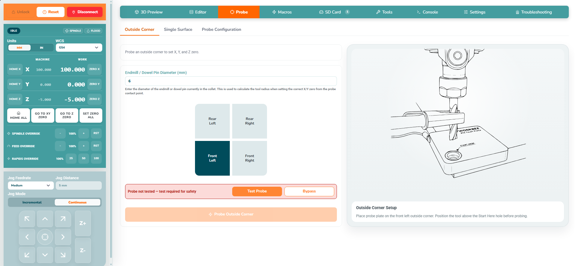
- Choose the actual front/rear and left/right stock corner. Place the probe plate as indicated on the relevant corner.
- Enter the diameter of the cutter or dowel pin actually in the collet.
- Position it above the plate’s Start Here hole as instructed by the probe guide.
- After the safety test passes, start Probe Outside Corner. Keep hands clear through every movement.
|
 |
- Wait for successful completion and all movement to stop. Keep the work zero set by probing. Do not press Zero or Set Zero All again.
- Remove the plate and clip, then raise the cutter clear of material and clamps.
- With the path clear, use Go to XY Zero to check alignment above the selected corner.
- To check the Z reference, use Go to Z Zero only once the path is clear. Z zero may be the material surface.
|
 |
| Instructions |
Preview |
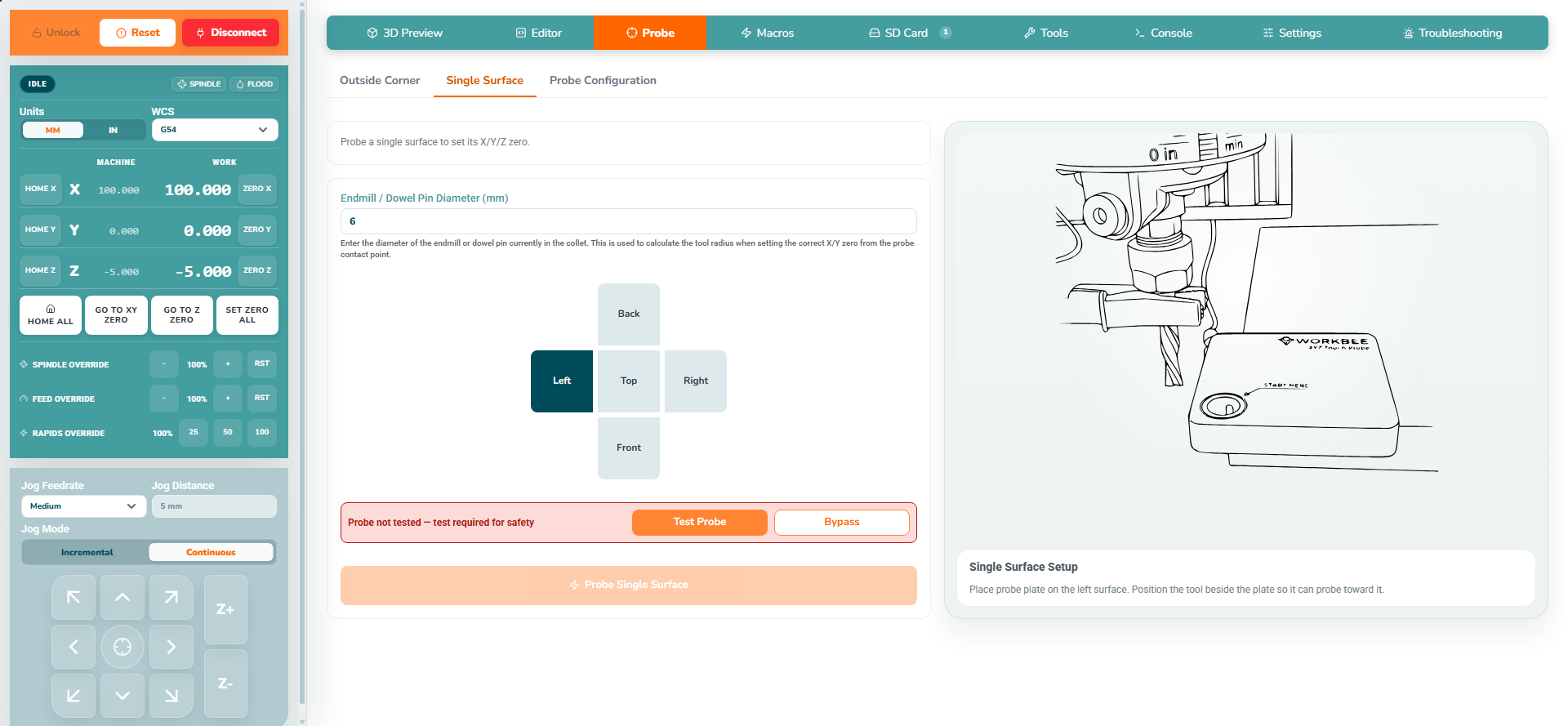
- Choose Left, Right, Front, Back or Top to match the face and plate position.
- Follow the displayed starting-position diagram. Place the tool on the approach side of that face with room for the search and retract.
- Run the safety test, then Probe Single Surface.
- The routine establishes only the selected axis, for example Z after a tool change. Do not manually zero it afterwards.
- Wait for movement to stop, remove the probe and clip, then raise clear before continuing.
|
 |
See First Job: touch probe setup for the physical front-left-corner sequence. Review the loaded program and pre-flight checks before cutting.