Use the Troubleshooting tab to check controller inputs, inspect hardware information and collect a report for Ooznest support.
Record the exact message and preceding action before resetting anything. Start with the read-only checks below; do not activate outputs to identify unfamiliar hardware.
| Symptom |
Start here |
| Cannot connect |
Check the appropriate USB, Wi-Fi or Ethernet guide. |
| Homing or limit alarm |
Read the message, then compare the stopped machine's switches with Signals. |
| Probe fails |
Check contact/release in Signals, then follow Test Probe. |
| G-code rejected |
Find the rejected line and response in Console, then see Alarms and errors. |
| Cause still unclear |
Export information for support with the exact symptom and steps that reproduce it. |
| Instructions |
Preview |
- Connect to the controller and open Troubleshooting.
- Select Signals, Power Supply, Spindles, RGB LED or Info.
- If investigating a fault, record its exact message and what you were doing before clearing it.
|
 |
| Instructions |
Preview |
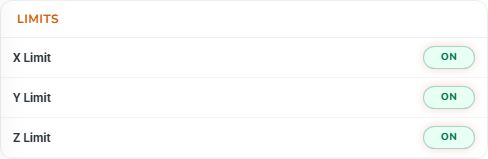
- Limits: shows the controller-reported X, Y and Z limit inputs. An A-axis input appears when enabled.
- ON: the controller reports the input active. OFF: it does not.
- With the machine stopped, compare the indicator with the corresponding accessible switch. Investigate an unexpected state before homing or running.
|
 |
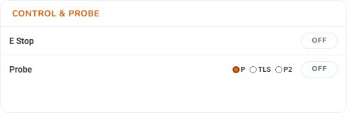
- Control & Probe: shows inputs such as E Stop, Door, Reset, Hold, Start and Probe. The rows shown depend on the connected firmware.
- P: primary probe. TLS: tool-length setter. P2: second probe.
- Selecting P, TLS or P2 changes the controller's probe selection; these are not display filters. Use only the selection matching your configured hardware.
- For a touch probe, check that contact and release change the Probe indication before using a probing routine. See the Probing guide for Test Probe and setup.
|
 |
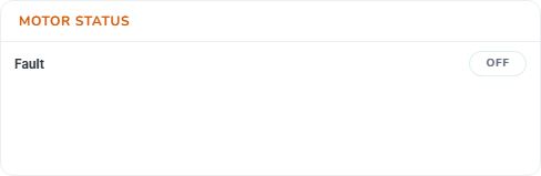
- Motor Status: shows motor Faults (Use onboard red led near motor connector to see which axis had the issue)
- Clear the cause of the error, then power cycle the controller to reset the fault.
|
 |
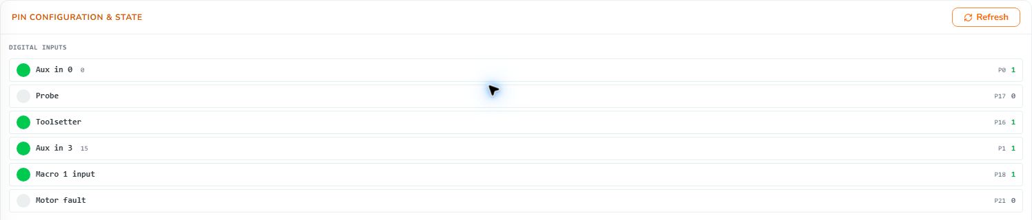
- Pin Configuration & State → Refresh: reads the controller's pin assignments and states.
- Digital Inputs: shows each input's label, hardware identifier, assigned P number and reported 0/1 state. The round indicator is green for 1 and grey for 0.
- Read the actual label and assignment on your controller. P numbers vary between configurations.
|
 |
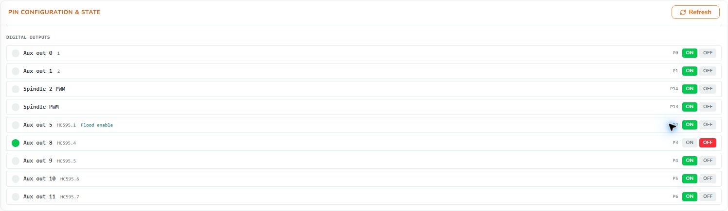
- Digital Outputs: shows output labels, hardware identifiers, P numbers and assigned functions where available.
- The round indicator shows the reported state. The coloured ON or OFF button is an available action, not a status light; the button matching the current state is disabled.
- Only test an output when you know what is connected and it is safe to activate. The buttons send real output commands immediately.
- Do not copy an example P number or assume that a label such as Aux out means nothing is connected.
|
 |
| Instructions |
Preview |
- Voltage: the latest reported supply voltage in volts. Current: the latest reported current in amperes.
- The chart shows recent received samples. Blue voltage uses the left scale; red current uses the right scale. Hover over the chart to inspect a sample.
|
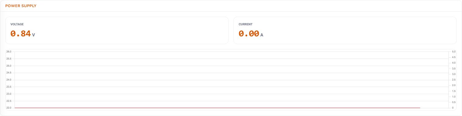 |
Set Active, the speed slider and ON/OFF send commands to the controller. Keep clear of the tool and use these only for a planned, safe test of the fitted toolhead.
| Instructions |
Preview |
- Click Refresh to read the controller's spindle list again.
- Active: identifies the selected spindle. Set Active: selects an enabled spindle for subsequent commands.
- A disabled selection means that spindle is not enabled in the controller settings. Do not select a different toolhead experimentally to resolve a fault.
|
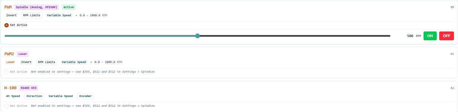 |
- Each card identifies the spindle name, interface/type, ID and RPM range where supplied.
- Badges identify firmware capabilities: Variable Speed, RPM Limits, Direction, At Speed, Invert and Laser.
- These describe the interface's capabilities; they do not confirm that the attached toolhead is wired, configured or operating correctly.
|
 |
- For an active spindle with a reported RPM range, move the speed slider to request a speed. Changes are sent immediately, so moving it can change the speed of a running spindle.
- The number beside the slider is the speed value used by these controls, not a measured spindle speed.
- ON: starts the selected spindle at the slider value. OFF: sends the spindle-stop command.
- A manually controlled router may still require its own switch and speed dial.
|
 |
| Instructions |
Preview |
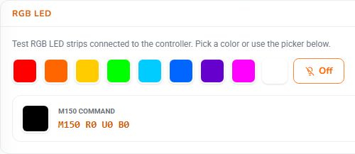
- Use this tab to test a supported RGB LED strip.
- Click a preset or the swatch beside M150 Command for a custom colour. The command is sent immediately; there is no Apply button.
- M150 Command shows the sent command: R is red, U green and B blue. Copy a suitable command for a macro if required.
- Off sends zero for all three channels. It stops the strip, not the controller or spindle.
|
 |
| Instructions |
Preview |
- Homing Status: shows whether the controller reports each available axis as HOMED.
- A dash means the axis is not marked HOMED in this display; check the controller connection and homing state.
- This is machine homing information. It does not establish the job's work zero.
|
 |
- Firmware: identifies the installed controller firmware, available version, Machine Config, decoded machine/accessories, board, SD-card status and available supply readings.
- If offered, Update now opens the controller firmware flasher. It does not update the desktop application.
- For an unconfigured controller, Run Configuration Wizard opens initial machine setup. Follow the First Connection and Setup guide.
|
 |
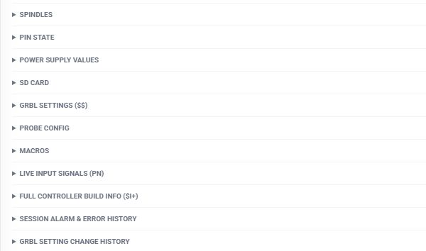
- Expand a diagnostic heading to inspect the controller's reported information.
- Use the matching section below for hardware, configuration or session-history evidence.
- Reported information identifies what the controller sees; it does not by itself identify the cause of a fault.
|
 |
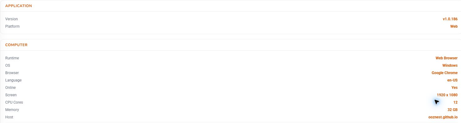
- Application: shows the Ooznest Control version and Web, Desktop or Mobile platform.
- Computer: shows the available operating system, browser/runtime, language, online state, screen size, processor count, memory and host information.
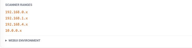
- Scanner Ranges: lists network ranges available to the scanner. WebUI Environment: expands the browser identification string. Desktop builds can also report network-adapter details.
|
 |
- Options: shows the firmware's reported options string.
- Include it with the other firmware details when support asks for controller information.
|
 |
¶ 7. Alarms and errors
| Instructions |
Preview |
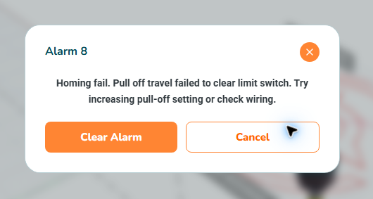
- An alarm prevents normal operation until its cause is addressed. Read the full message before clearing it.
- In this Alarm 8 example, the limit switch did not clear during homing pull-off. Check the switch, wiring and pull-off setup before retrying.
- Clearing an alarm does not repair the cause. Home again if position may have been lost, then check work zero before restarting.
|
 |
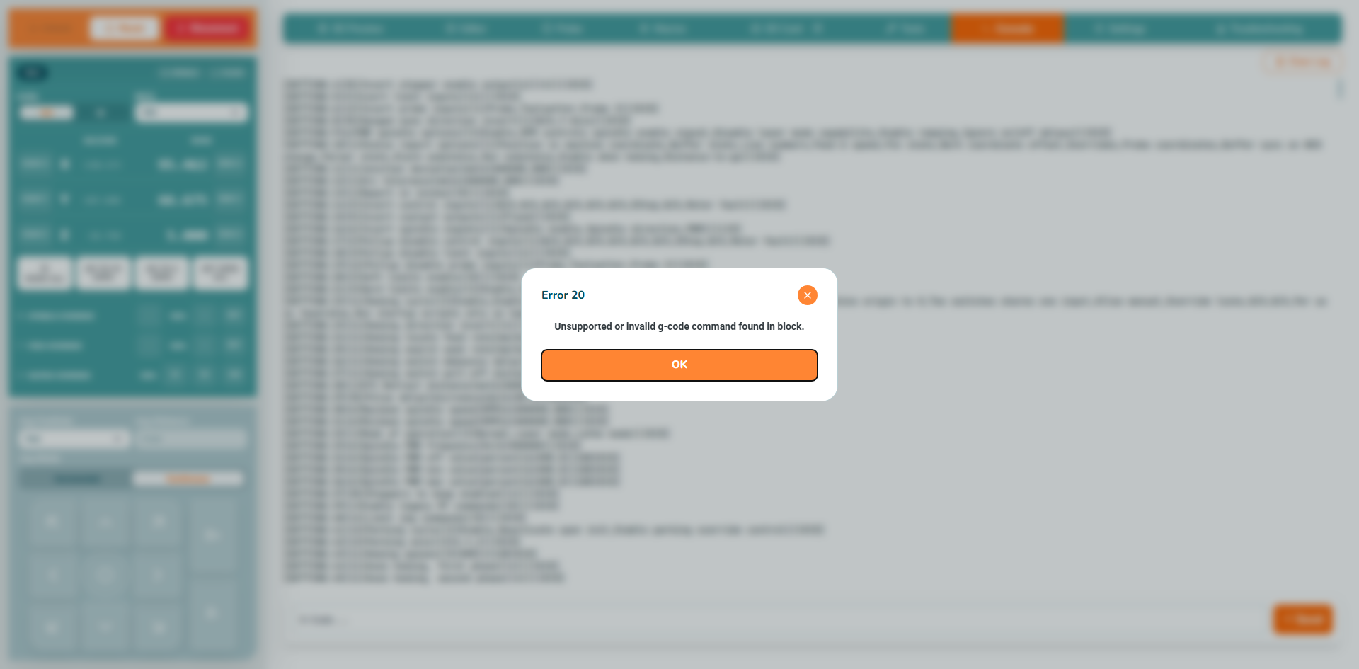
- An error rejects a command or G-code line.
- Error 20 means an unsupported or invalid G-code command was found. Find the rejected line in the Console and check the program or CAM postprocessor.
- Correct the cause before restarting. Clicking OK only dismisses the message.
|
 |
| Instructions |
Preview |
- Click Export Troubleshooting Information to download a ZIP containing a JSON diagnostic snapshot.
- Connect first to include the available machine information. An export without a controller connection still includes available computer information.
- Send the ZIP to Ooznest support with a description of the problem, exact messages and the actions that triggered it. Exporting downloads a file; it does not send it to support automatically.
- The report can include settings, macros, network identifiers and credentials where present. Share it privately with support rather than posting it publicly.
|
 |
After a targeted test, confirm the original symptom is resolved before returning to cutting. Otherwise, contact Ooznest support and send the exported ZIP privately. Include the machine/controller model, application version, connection type, exact message, triggering action and whether the fault repeats. Exporting alone does not contact support.
Use the Console to inspect controller messages, or return to First Job after resolving the fault.